 0755-23179541
  sales@oyii.net
.png) 8618926041961
8618926041961
1.25Gbps 1550nm 60Km LC DDM
SFP Transceiver
1.25Gbps 1550nm 60Km LC DDM
Product Features
1. SFP package with LC connector.
2. 1550nm DFB laser and PIN photo detector.
3. Up to 60Km transmission on SMF.
4. +3.3V single power supply.
5. LVPECL compatible data input/output interface.
6. Low EMI and excellent ESD protection.
7. laser safety standard IEC-60825 compliant.
8. Compatible with RoHS.
9. Digital Diagnostic SFF-8472 compliant.
10. Signal Ground Isolated to Case.
Application
1. 1.25Gb/s 1000Base-LX Ethernet.
2. Dual Rate 1.06 / 2.125 Gb/s Fiber Channel.
Absolute Maximum Ratings:
|
Parameter |
Symbol |
Minimum |
Maximum |
Units |
|
Storage Temperature |
Tst |
-40 |
+85 |
℃ |
|
Supply Voltage |
Vcc |
0 |
+3.6 |
V |
|
Operating Relative Humidity |
RH |
5 |
95 |
% |
Operation Environment:
|
Parameter |
Symbol |
Min |
Typical |
Max |
Units |
|
Supply Voltage |
Vcc |
3.15 |
3.3 |
3.45 |
V |
|
Operating Case Temperature |
Tc |
0 |
|
+70 |
|
|
Power Dissipation |
|
|
|
1 |
W |
|
Data Rate |
|
|
1.25 |
|
Gbps |
Optical Characteristics
(Ambient Operating Temperature 0℃ to +70℃, Vcc =3.3 V)
|
Parameter |
Symbol |
Min. |
Typ. |
Max. |
Units |
|
Transmitter Section |
|||||
|
Center Wavelength |
λo |
1540 |
1550 |
1560 |
nm |
|
Spectral Width (RMS) |
△λ |
- |
- |
1 |
nm |
|
Average Output Power |
Po |
-5 |
- |
0 |
dBm |
|
Extinction Ratio |
Er |
8 |
- |
|
dB |
|
Rise/Fall Time (20%~80%) |
Tr/Tf |
|
|
180 |
ps |
|
Total jitter |
Tj |
|
|
0.43 |
UI |
|
Optical Eye Diagram |
IEEE 802.3z and ANSI Fiber Channel Compatible |
||||
|
Receiver Section |
|||||
|
Center Wavelength |
λo |
1260 |
|
1620 |
nm |
|
Receiver Sensitivity |
Rsen |
|
|
-24 |
dBm |
|
Receiver Overload |
Rov |
-3 |
|
|
dBm |
|
Return Loss |
|
12 |
|
|
dB |
|
LOS Assert |
LOSA |
-36 |
|
|
dBm |
|
LOS Dessert |
LOSD |
|
|
-25 |
dBm |
|
LOS Hysteresis |
|
0.5 |
|
5 |
|
Electrical Characteristics
(Ambient Operating Temperature 0℃ to +70℃, Vcc =3.3 V)
|
Parameter |
Symbol |
Min. |
Typ. |
Max. |
unit |
|
|
Transmitter Section |
||||||
|
Input Differential Impendence |
Zin |
90 |
100 |
110 |
Ohm |
|
|
Data Input Swing Differential |
Vin |
500 |
|
2400 |
mV |
|
|
TX Disable |
Disable |
|
2.0 |
|
Vcc |
V |
|
Enable |
|
0 |
|
0.8 |
V |
|
|
TX Fault |
Assert |
|
2.0 |
|
Vcc |
V |
|
Deassert |
|
0 |
|
0.8 |
V |
|
|
Receiver Section |
||||||
|
Output differential impendence |
Zout |
|
100 |
|
Ohm |
|
|
Data Input Swing Differential |
Vout |
370 |
|
2000 |
mV |
|
|
Rx_LOS |
Assert |
|
2.0 |
|
Vcc |
V |
|
Deassert |
|
0 |
|
0.8 |
V |
|
EEPROM INFORMATION(A0)
|
Addr |
Field Size (Bytes) |
Name of Field |
HEX |
Description |
|
0 |
1 |
Identifier |
03 |
SFP |
|
1 |
1 |
Ext. Identifier |
04 |
MOD4 |
|
2 |
1 |
Connector |
07 |
LC |
|
3-10 |
8 |
Transceiver |
00 00 00 02 12 00 0D 01 |
Transmitter Code |
|
11 |
1 |
Encoding |
01 |
8B10B |
|
12 |
1 |
BR, nominal |
0D |
1250M bps |
|
13 |
1 |
Reserved |
00 |
|
|
14 |
1 |
Length (9um)-km |
3C |
60km |
|
15 |
1 |
Length (9um) |
64/C8/FF |
|
|
16 |
1 |
Length (50um) |
00 |
|
|
17 |
1 |
Length (62.5um) |
00 |
|
|
18 |
1 |
Length (copper) |
00 |
|
|
19 |
1 |
Reserved |
00 |
|
|
20-35 |
16 |
Vendor name |
57 49 4E 54 4F 50 20 20 20 20 20 20 20 20 20 20 |
WINTOP |
|
36 |
1 |
Reserved |
00 |
|
|
37-39 |
3 |
Vendor OUI |
00 00 00 |
|
|
40-55 |
16 |
Vendor PN |
xx xx xx xx xx xx xx xx xx xx xx xx xx xx xx xx |
ASC II |
|
56-59 |
4 |
Vendor rev |
31 2E 30 20 |
V1.0 |
|
60-61 |
2 |
Wavelength |
06 0E |
1550nm |
|
62 |
1 |
Reserved |
00 |
|
|
63 |
1 |
CC BASE |
XX |
Check sum of byte 0~62 |
|
64-65 |
2 |
Options |
00 1A |
LOS, TX_DISABLE, TX_FAULT |
|
66 |
1 |
BR, max |
32 |
50% |
|
67 |
1 |
BR, min |
32 |
50% |
|
68-83 |
16 |
Vendor SN |
00 00 00 00 00 00 00 00 00 00 00 00 00 00 00 00 |
Unspecified |
|
84-91 |
8 |
Vendor date code |
XX XX XX 20 |
Year, Month, Day |
|
92-94 |
3 |
Reserved |
00 |
|
|
95 |
1 |
CC_EXT |
XX |
Check sum of byte 64~94 |
|
96-255 |
160 |
Vendor specific |
|
Diagnostics
|
Parameter |
Range |
Accuracy |
Unit |
Calibration |
|
Temperature |
0~70 |
±3 |
℃ |
Internal |
|
Voltage |
3.15~3.45 |
0.1 |
V |
Internal |
|
Bias Current |
10~80 |
±2 |
mA |
Internal |
|
Tx Power |
-6~1 |
±2 |
dBm |
Internal |
|
Rx Power |
-26~-3 |
±3 |
dBm |
Internal |
Pin Description
|
Pins |
Name |
Description |
NOTE |
|
1 |
VeeT |
Transmitter Ground |
|
|
2 |
Tx Fault |
Transmitter Fault Indication |
1 |
|
3 |
Tx Disable |
Transmitter Disable |
2 |
|
4 |
MOD DEF2 |
Module Definition 2 |
3 |
|
5 |
MOD DEF1 |
Module Definition 1 |
3 |
|
6 |
MOD DEF0 |
Module Definition 0 |
3 |
|
7 |
Rate Select |
Not Connected |
|
|
8 |
LOS |
Loss of Signal |
4 |
|
9 |
VeeR |
Receiver Ground |
|
|
10 |
VeeR |
Receiver Ground |
|
|
11 |
VeeR |
Receiver Ground |
|
|
12 |
RD- |
Inv. Received Data Output |
S |
|
13 |
RD+ |
IReceived Data Output |
S |
|
14 |
VeeR |
Receiver Ground |
|
|
15 |
VccR |
Receiver Power |
|
|
16 |
VccT |
Transmitter Power |
|
|
17 |
VeeT |
Transmitter Ground |
|
|
18 |
TD+ |
Transmit Data Input |
6 |
|
19 |
TD- |
Inv. Transmit Data Input |
6 |
|
20 |
VeeT |
Transmitter Ground |
Notes:
1. TX Fault is an open collector output, which should be pulled up with a 4.7k~10kΩ resistor on the host board to a voltage between 2.0V and Vcc+0.3V. Logic 0 indicates normal operation; logic 1 indicates a laser fault of some kind. In the low state, the output will be pulled to less than 0.8V.
2. TX Disable is an input that is used to shut down the transmitter optical output. It is pulled up with in the module with a 4.7k~10kΩ resistor. Its states are:
Low (0~0.8V): Transmitter on
(>0.8V, <2.0V): Undefined
High (2.0~3.3V): Transmitter Disabled
Open: Transmitter Disabled
3. MOD-DEF 0,1,2 are the module definition pins. They should be pulled up with a 4.7k~10kΩresistor on the host board. The pull-up voltage shall be VccT or VccR.
MOD-DEF 0 is grounded by the module to indicate that the module is present.
MOD-DEF 1 is the clock line of two wire serial interface for serial ID.
MOD-DEF 2 is the data line of two wire serial interface for serial ID.
4. LOS is an open collector output, which should be pulled up with a 4.7k~10kΩ resistor on the host board to a voltage between 2.0V and Vcc+0.3V. Logic 0 indicates normal operation; logic 1 indicates loss of signal. In the low state, the output will be pulled to less than 0.8V.
5. These are the differential receiver output. They are internally AC-coupled 100Ω differential lines which should be terminated with 100Ω (differential) at the user SERDES.
6. These are the differential transmitter inputs. They are AC-coupled, differential lines with 100Ω differential termination inside the module.
Recommended Application Circuit

Outline Dimensions (mm)

-

OYI3434G4R
ONU product is the terminal equipment of a series of XPON which comply fully with ITU-G.984.1/2/3/4 standard and meet the energy-saving of G.987.3 protocol,ONU is based on mature and stable and high cost-effective GPON technology which adopts high-performance XPON REALTEK chipset and has high reliability , easy management, flexible configuration, robustness, good quality service guarantee(Qos). -
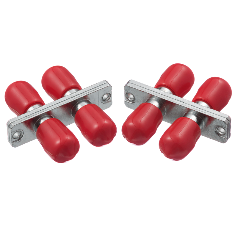
ST Type
Fiber optic adapter, sometimes also called a coupler, is a small device designed to terminate or link fiber optic cables or fiber optic connectors between two fiber optic lines. It contains the interconnect sleeve that holds two ferrules together. By precisely linking two connectors, fiber optic adapters allow the light sources to be transmitted at their maximum and minimize the loss as much as possible. At the same time, fiber optic adapters have the advantages of low insertion loss, good interchangeability, and reproducibility. They are used to connect optical fiber connectors such as FC, SC, LC, ST, MU, MTRJ, D4, DIN, MPO, etc. They are widely used in optical fiber communications equipment, measuring appliances, and so on. The performance is stable and reliable. -
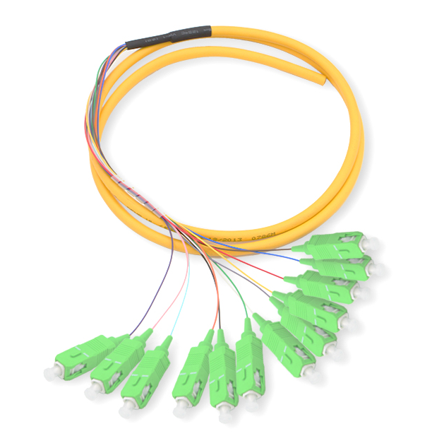
SC/APC SM 0.9MM 12F
Fiber optic fanout pigtails provide a swift method for creating communication devices in the field. They are designed, manufactured, and tested according to protocols and performance standards set by the industry, meeting your most stringent mechanical and performance specifications. The fiber optic fanout pigtail is a length of fiber cable with a multi-core connector fixed on one end. It can be divided into single mode and multi mode fiber optic pigtail based on the transmission medium; it can be divided into FC, SC, ST, MU, MTRJ, D4, E2000, LC, etc., based on the connector structure type; and it can be divided into PC, UPC, and APC based on the polished ceramic end-face. Oyi can provide all kinds of optic fiber pigtail products; the transmission mode, optical cable type, and connector type can be customized as needed. It offers stable transmission, high reliability, and customization, making it widely used in optical network scenarios such as central offices, FTTX, and LAN, etc. -
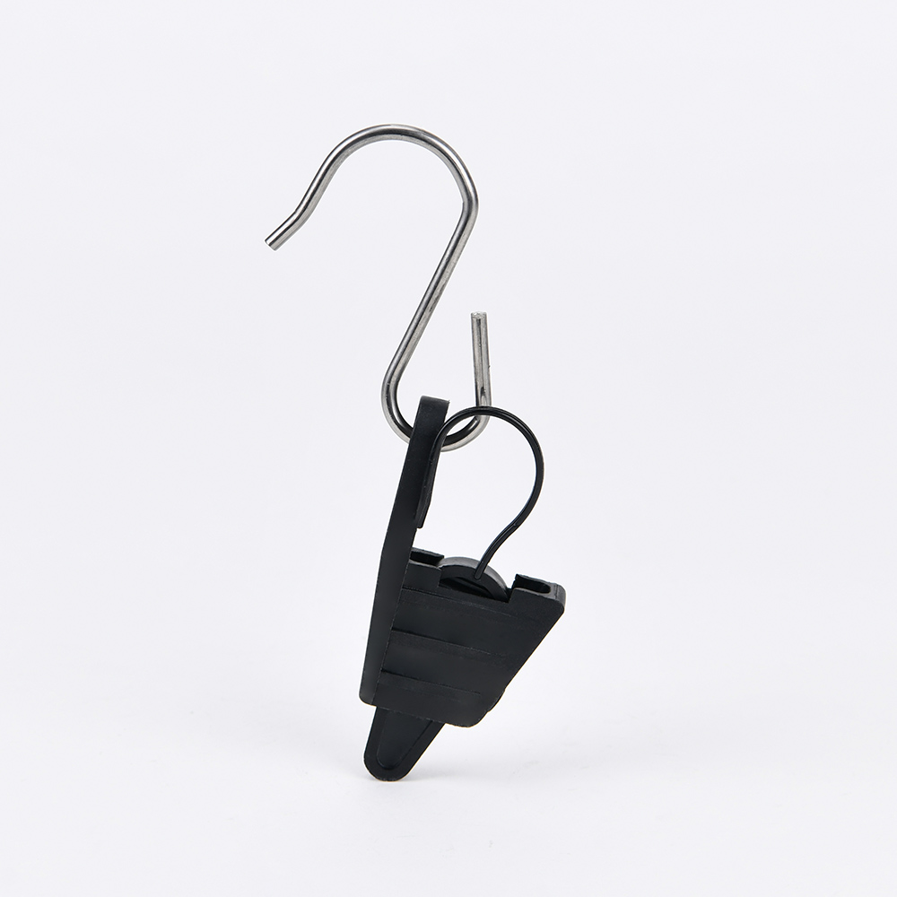
FTTH Drop Cable Suspension Tension Clamp S Hook
FTTH fiber optic drop cable suspension tension clamp S hook clamps are also called insulated plastic drop wire clamps. The design of the dead-ending and suspension thermoplastic drop clamp includes a closed conical body shape and a flat wedge. It is connected to the body through a flexible link, ensuring its captivity and an opening bail. It is a kind of drop cable clamp that is widely used for both indoor and outdoor installations. It is provided with a serrated shim to increase hold on the drop wire and used to support one and two pair telephone drop wires at span clamps, drive hooks, and various drop attachments. The prominent advantage of the insulated drop wire clamp is that it can prevent electrical surges from reaching the customer premises. The working load on the support wire is effectively reduced by the insulated drop wire clamp. It is characterized by good corrosion resistant performance, good insulating properties, and long life service. -

OYI H Type Fast Connector
Our fiber optic fast connector, the OYI H type, is designed for FTTH (Fiber to The Home), FTTX (Fiber to the X). It is a new generation of fiber connector used in assembly that provides open flow and precast types, meeting the optical and mechanical specifications of standard optical fiber connectors. It is designed for high quality and high efficiency during installation.Hot-melt quickly assembly connector is directly with a grinding of the ferrule connector directly with the falt cable 2*3.0MM /2*5.0MM/2*1.6MM, round cable 3.0MM,2.0MM,0.9MM, using a fusion splice, the splicing point inside the connector tail, the weld is no need for additional protection. It can improve the optical performance of the connector. -
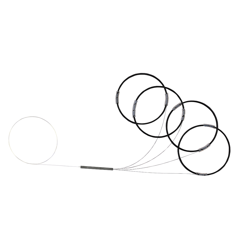
Bare Fiber Type Splitter
A fiber optic PLC splitter, also known as a beam splitter, is an integrated waveguide optical power distribution device based on a quartz substrate. It is similar to a coaxial cable transmission system. The optical network system also requires an optical signal to be coupled to the branch distribution. The fiber optic splitter is one of the most important passive devices in the optical fiber link. It is an optical fiber tandem device with many input terminals and many output terminals, and is especially applicable to a passive optical network (EPON, GPON, BPON, FTTX, FTTH, etc.) to connect the ODF and the terminal equipment and to achieve the branching of the optical signal.
If you're looking for a reliable, high-speed fibre optic cable solution, look no further than OYI. Contact us now to see how we can help you stay connected and take your business to the next level.
