 0755-23179541
  sales@oyii.net
.png) 8618926041961
8618926041961
SFP-ETRx-4
10/100/1000 BASE-T Copper SFP Transceiver
SFP-ETRx-4
Product Features
1.Up to 1.25 Gb/s bi-directional data links.
2.Link lengths at 1.25 Gb/s up to 100 meters.
3.10/100/1000 BASE-T operation in host systems with SGMII interface.
4.Support TX- disable and Link function.
5.Compliant with SFP MSA.
6.Compact RJ-45 connector assembly.
7.Hot-pluggable SFP Footprint.
8.Single + 3.3V Power Supply.
9.Fully Metallic Enclosure for Low EMI.
10.Low power dissipation (1.05W typical).
11.RoHS compliant and lead-free.
12.Operating case temperature Commercial: 0 ~ +70oC.
Extended: -10 ~ +80oC.
Industrial: -40 ~ +85oC.
Technical Specifications
1.LAN 1000Base-T.
2.Switch to Switch Interface.
3.Router/Server interface.
4.witched backplane applications.
|
Part Number |
Data Rate (Mb/s) |
Transmission Distance(m) |
Link Indicator on RX-LOS pin |
TX-disable with PHY |
Temperature (oC) (Operating Case) |
|
OPT-ETRC-4 |
10/100/1000 |
100 |
Yes |
Yes |
0~70 commercial |
|
OPT-ETRE-4 |
10/100/1000 |
100 |
Yes |
Yes |
-10~80 Extended |
|
OPT-ETRI-4 |
10/100/1000 |
100 |
Yes |
Yes |
-40~85 Industrial |
1. Absolute Maximum Ratings
It has to be noted that the operation in excess of any individual absolute maximum ratings might cause permanent damage to this module.
|
Parameter |
Symbol |
Min |
Max |
Unit |
Notes |
|
Storage Temperature |
TS |
-40 |
85 |
oC |
|
|
Power Supply Voltage |
VCC |
-0.5 |
3.6 |
V |
|
|
Relative Humidity (non-condensation) |
RH |
5 |
95 |
% |
2.Recommended Operating Conditions and Power Supply Requirements
| Parameter | Symbol | Min | Typical | Max | Unit | Notes |
| Operating Case Temperature | TOP | 0 | 70 | oC | commercial | |
| -10 | 80 | extended | ||||
| -40 | 85 | industrial | ||||
| Power Supply Voltage | VCC | 3.135 | 3.3 | 3.465 | V | |
| Data Rate | 10 | 1000 | Mb/s | |||
| Link Distance (SMF) | D | 100 | m |
3. Pin Assignment and Pin Description

Figure1. Diagram of host board connector block pin numbers and names.
|
PIN |
Name |
Name/Description |
Notes |
|
1 |
VEET |
Transmitter Ground (Common with Receiver Ground) |
1 |
|
2 |
TXFAULT |
Transmitter Fault. |
|
|
3 |
TXDIS |
Transmitter Disable. Laser output disabled on high or open. |
|
|
4 |
MOD-DEF (2) |
Module Definition 2. Data line for Serial ID. |
2 |
|
5 |
MOD-DEF (1) |
Module Definition 1. Clock line for Serial ID. |
2 |
|
6 |
MOD-DEF (0) |
Module Definition 0. Grounded within the module. |
2 |
|
7 |
Rate Select |
No connection required |
|
|
8 |
LOS |
Loss of Signal indication. Logic 0 indicates normal operation. |
3 |
|
9 |
VEER |
Receiver Ground (Common with Transmitter Ground) |
1 |
|
10 |
VEER |
Receiver Ground (Common with Transmitter Ground) |
1 |
|
11 |
VEER |
Receiver Ground (Common with Transmitter Ground) |
1 |
|
12 |
RD- |
Receiver Inverted DATA out. AC Coupled |
|
|
13 |
RD+ |
Receiver Non-inverted DATA out. AC Coupled |
|
|
14 |
VEER |
Receiver Ground (Common with Transmitter Ground) |
1 |
|
15 |
VCCR |
Receiver Power Supply |
|
|
16 |
VCCT |
Transmitter Power Supply |
|
|
17 |
VEET |
Transmitter Ground (Common with Receiver Ground) |
1 |
|
18 |
TD+ |
Transmitter Non-Inverted DATA in. AC Coupled. |
|
|
19 |
TD- |
Transmitter Inverted DATA in. AC Coupled. |
|
|
20 |
VEET |
Transmitter Ground (Common with Receiver Ground) |
1 |
Notes:
1.Circuit ground is connected to chassis ground.
2.Should be pulled up with 4.7k - 10k Ohms on host board to a voltage between 2.0 V and 3.6 V.
MOD-DEF (0) pulls line low to indicate module is plugged in.
3.LVTTL compatible with a maximum voltage of 2.5V.
4. Power Supply Interface Electronic Characteristics
The OPT-ETRx-4 has an input voltage range of 3.3 V ± 5%. The 4 V maximum voltage is not allowed for continuous operation.
|
Parameter |
Symbol |
Min |
Typical |
Max |
Unit |
Notes |
|
Power Consumption |
|
|
|
1.2 |
W |
|
|
Supply Current |
Icc |
|
|
375 |
mA |
|
|
Input Voltage Tolerance |
|
-0.3 |
|
4.0 |
V |
|
|
Surge |
Surge |
|
30 |
|
mV |
|
|
Current |
|
current See caution note |
|
|||
Notes: Power consumption and surge current are higher than the specified values in the SFP MSA.
5. Low-Speed Signals Electronic Characteristics
MOD-DEF (1) (SCL) and MOD-DEF (2) (SDA) are open drain CMOS signals. Both MOD-DEF (1) and MOD-DEF (2) must be pulled up to host-VCC.
|
Parameter |
Symbol |
Min |
Typical |
Max |
Unit |
Notes |
|
SFP Output LOW |
VOL |
0 |
|
0.5 |
V |
4.7k to 10k pull-up to host-Vcc. |
|
SFP Output HIGH |
VOH |
Host-Vcc -0.5 |
|
Host-Vcc +0.3 |
V |
4.7k to 10k pull-up to host-Vcc. |
|
SFP Input LOW |
VIL |
0 |
|
0.8 |
V |
4.7k to 10k pull-up to Vcc. |
|
SFP Input HIGH |
VIH |
2 |
|
Vcc + 0.3 |
V |
4.7k to 10k pull-up to Vcc. |
6. High-Speed Electrical Interface
All high-speed signals are AC-coupled internally.
|
High-Speed Electrical Interface, Transmission Line-SFP |
||||||
|
Parameter |
Symbol |
Min |
Typical |
Max |
Unit |
Notes |
|
Line Frequency |
FL |
|
125 |
|
MHz |
5-level encoding, pe IEEE 802.3 |
|
Tx Output Impedance |
Zout, TX |
|
100 |
|
Ohm |
Differential |
|
Rx Input Impedance |
Zin,RX |
|
100 |
|
Ohm |
Differential |
|
|
High-Speed Electrical Interface, Host-SFP |
|||||
|
Single Ended Data Input Swing |
Vinsing |
250 |
|
1200 |
mv |
Single ended |
|
Single Ende Data Output Swing |
Voutsing |
350 |
|
800 |
mv |
Single ended |
|
Rise/Fall Time |
Tr, TF |
|
175 |
|
PS |
20%-80% |
|
Tx Input Impedance |
Zin |
|
50 |
|
Ohm |
Single ended |
|
Rx Output Impedance |
Zout |
|
50 |
|
Ohm |
Single ended |
7. General Specifications
|
Parameter |
Symbol |
Min |
Typical |
Max |
Unit |
Notes |
|
Data Rate |
BR |
10 |
|
1000 |
Mb/s |
IEEE 802.3 compatible |
|
Cable Length |
L |
|
|
100 |
m |
Category 5 UTP. BER <10-12 |
Notes:
1.Clock tolerance is +/- 50 ppm.
2.By default, the OPT-ETRx-4 is a full duplex device in preferred master mode.
3.Automatic crossover detection is enabled. External crossover cable is not required.
4.By default, 1000 BASE-T operation requires the host system to have an SERDES interface with no clocks.
8. Serial Communication Protocol
OPT-ETRx-4 supports the 2-wire serial communication protocol outlined in the SFP MSA. It uses an Atmel AT24C02D 256byte EEPROM with an address of A0h.
|
Parameter |
Symbol |
Min |
Typical |
Max |
Unit |
Notes |
|
12C Clock Rate |
|
0 |
|
100000 |
Hz |
-

SFP-ETRx-4
The ER4 is a transceiver module designed for 40km optical communication applications. The design is compliant to 40GBASE-ER4 of the IEEE P802.3ba standard. The module converts 4 inputs channels (ch) of 10Gb/s electrical data to 4 CWDM optical signals, and multiplexes them into a single channel for 40Gb/s optical transmission. Reversely, on the receiver side, the module optically demultiplexes a 40Gb/s input into 4 CWDM channels signals, and converts them to 4 channel output electrical data. -

OYI-OW2 series Type
Outdoor Wall-mount Fiber Optic Distribution Frame is mainly used for connecting the outdoor optical cables, optical patch cords and optical pigtails. It can be wall mounted or pole mounted, and facilitates the test and refit of the lines. It is an integrated unit for fiber management, and can be used as distribution box. This equipment function is to fix and manage the fiber optic cables inside the box as well as provide protection. Fiber optic termination box is modular so they are applying cable to your existing systems without any modification or additional work. Suitable for installation of FC, SC, ST, LC, etc. adaptors, and suitable for fiber optic pigtail or plastic box type PLC splitters and large working space to integrate the pigtails, cables and adapters. -
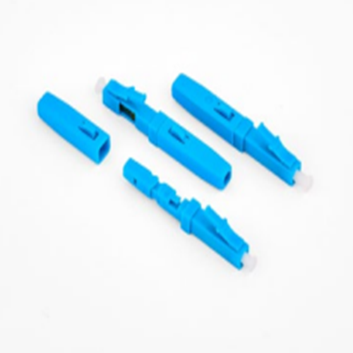
OYI G type Fast Connector
Our Fiber optic fast connector OYI G type designed for FTTH(Fiber To The Home). It is a new generation of fiber connector used in assembly. It can provide open flow and precast type, which optical and mechanical specification meets the standard optical fiber connector. It is designed for high quality and high efficiency for installation. Mechanical connectors make fiber terminaitons quick, easy and reliable. These fiber optic connectors offer terminations without any hassles and require no epoxy, no polishing, no splicing, no heating and can achieve similar excellent transmission parameters as standard polishing and spicing technology. Our connector can greatly reduce the assembly and setup time. The pre-polished connectors are mainly applied to FTTH cable in FTTH projects, directly in the end user site. -

Optic Fiber Terminal Box
Design of hinge and convenient press-pull button lock. -
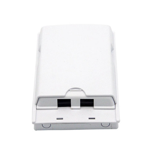
OYI-ATB02B Desktop Box
OYI-ATB02B double-port terminal box is developed and produced by the company itself. The product’s performance meets the requirements of industry standards YD/T2150-2010. It is suitable for installing multiple types of modules and can be applied to the work area wiring subsystem to achieve dual-core fiber access and port output. It provides fiber fixing, stripping, splicing, and protection devices, and allows for a small amount of redundant fiber inventory, making it suitable for FTTD (fiber to the desktop) system applications. It uses embedded surface frame, easy to install and disassemble, it is with protective door and dusty free. The box is made of high-quality ABS plastic through injection molding, making it anti-collision, flame retardant, and highly impact-resistant. It has good sealing and anti-aging properties, protecting the cable exit and serving as a screen. It can be installed on the wall. -

OYI I Type Fast Connector
SC field assembled melting free physical connector is a kind of quick connector for physical connection. It uses special optical silicone grease filling to replace the easy-to-lose matching paste. It is used for quick physical connection (not matching paste connection) of small equipment. It is matched with a group of optical fiber standard tools. It is simple and accurate to complete the standard end of optical fiber and reaching the physical stable connection of optical fiber. The assembly steps are simple and low skills required. the connection success rate of our connector is nearly 100%, and the service life is more than 20 years.
If you're looking for a reliable, high-speed fibre optic cable solution, look no further than OYI. Contact us now to see how we can help you stay connected and take your business to the next level.
