 0755-23179541
  sales@oyii.net
.png) 8618926041961
8618926041961
SFP-ETRx-4
10/100/1000 BASE-T Copper SFP Transceiver
SFP-ETRx-4
Product Description
The ER4 is a transceiver module designed for 40km optical communication applications. The design is compliant to 40GBASE-ER4 of the IEEE P802.3ba standard. The module converts 4 inputs channels (ch) of 10Gb/s electrical data to 4 CWDM optical signals, and multiplexes them into a single channel for 40Gb/s optical transmission. Reversely, on the receiver side, the module optically demultiplexes a 40Gb/s input into 4 CWDM channels signals, and converts them to 4 channel output electrical data.
The central wavelengths of the 4 CWDM channels are 1271, 1291, 1311 and 1331 nm as members of the CWDM wavelength grid defined in ITU-T G694.2. It contains a duplex LC Adapter for the optical interface and a 38-pin adapter for the electrical interface. To minimize the optical dispersion in the long-haul system, single-mode fiber (SMF) has to be applied in this module.
The product is designed with form factor, optical/electrical connection and digital diagnostic interface according to the QSFP Multi-Source Agreement (MSA). It has been designed to meet the harshest external operating conditions including temperature, humidity and EMI interference.
The module operates from a single +3.3V power supply and LVCMOS/LVTTL global control signals such as Module Present, Reset, Interrupt and Low Power Mode are available with the modules. A 2-wire serial interface is available to send and receive more complex control signals and to obtain digital diagnostic information. Individual channels can be addressed and unused channels can be shut down for maximum design flexibility.
The TQP10 is designed with form factor, optical/electrical connection and digital diagnostic interface according to the QSFP Multi-Source Agreement (MSA). It has been designed to meet the harshest external operating conditions including temperature, humidity and EMI interference. The module offers very high functionality and feature integration, accessible via a two-wire serial interface.
Product Features
1. 4 CWDM lanes MUX/DEMUX design.
2. Up to 11.2Gbps per channel bandwidth.
3. Aggregate bandwidth of > 40Gbps.
4. Duplex LC connector.
5. Compliant with 40G Ethernet IEEE802.3ba and 40GBASE-ER4 Standard.
6. QSFP MSA compliant.
7. APD photo-detector.
8. Up to 40 km transmission.
9. Compliant with QDR/DDR Infini band data rates.
10. Single +3.3V power supply operating.
11. Built-in digital diagnostic functions.
12. Temperature range 0°C to 70°C.
13. RoHS Compliant Part.
Applications
1. Rack to rack.
2. Data centers Switches and Routers.
3. Metro networks.
4. Switches and Routers.
5. 40G BASE-ER4 Ethernet Links.
|
Transmitter |
|
|
|
|
|
||
|
Single Ended Output Voltage Tolerance |
|
0.3 |
|
4 |
V |
1 |
|
|
Common mode Voltage Tolerance |
|
15 |
|
|
mV |
|
|
|
Transmit Input Diff Voltage |
VI |
150 |
|
1200 |
mV |
|
|
|
Transmit Input Diff Impedance |
ZIN |
85 |
100 |
115 |
|
|
|
|
Data Dependent Input Jitter |
DDJ |
|
0.3 |
|
UI |
|
|
|
|
Receiver |
|
|
|
|
|
|
|
Single Ended Output Voltage Tolerance |
|
0.3 |
|
4 |
V |
|
|
|
Rx Output Diff Voltage |
Vo |
370 |
600 |
950 |
mV |
|
|
|
Rx Output Rise and Fall Voltage |
Tr/Tf |
|
|
35 |
ps |
1 |
|
|
Total Jitter |
TJ |
|
0.3 |
|
UI |
|
|
Note:
1.20~80%
Optical Parameters (TOP = 0 to 70 °C, VCC = 3.0 to 3.6 Volts)
|
Parameter |
Symbol |
Min |
Typ |
Max |
Unit |
Ref. |
|
|
Transmitter |
|
|
|||
|
Wavelength Assignment |
L0 |
1264.5 |
1271 |
1277.5 |
nm |
|
|
L1 |
1284.5 |
1291 |
1297.5 |
nm |
|
|
|
L2 |
1304.5 |
1311 |
1317.5 |
nm |
|
|
|
L3 |
1324.5 |
1331 |
1337.5 |
nm |
|
|
|
Side-mode Suppression Ratio |
SMSR |
30 |
- |
- |
dB |
|
|
Total Average Launch Power |
PT |
- |
- |
10.5 |
dBm |
|
|
Transmit OMA per Lane |
TxOMA |
0 |
|
5.0 |
dBm |
|
|
Average Launch Power, each Lane |
TXPx |
0 |
|
5.0 |
dBm |
|
|
Difference in Launch Power between any two Lanes (OMA) |
|
- |
- |
4.7 |
dB |
|
|
TDP, each Lane |
TDP |
|
|
2.6 |
dB |
|
|
Extinction Ratio |
ER |
5.5 |
6.5 |
|
dB |
|
|
Transmitter Eye Mask Definition {X1, X2, X3, Y1, Y2, Y3} |
|
{0.25,0.4,0.45,0.25,0.28,0.4} |
|
|
||
|
Optical Return Loss Tolerance |
|
- |
- |
20 |
dB |
|
|
Average Launch Power OFF Transmitter, each Lane |
Poff |
|
|
-30 |
dBm |
|
|
Relative Intensity Noise |
Rin |
|
|
-128 |
dB/HZ |
1 |
|
Optical Return Loss Tolerance |
|
- |
- |
12 |
dB |
|
|
|
Receiver |
|
|
|||
|
Damage Threshold |
THd |
0 |
|
|
dBm |
1 |
|
Receiver Sensitivity (OMA) per Lane |
Rxsens |
-21 |
|
-6 |
dBm |
|
|
Receiver Power (OMA), each Lane |
RxOMA |
- |
- |
-4 |
dBm |
|
|
Stressed Receiver Sensitivity (OMA) per Lane |
SRS |
|
|
-16.8 |
dBm |
|
|
RSSI Accuracy |
|
-2 |
|
2 |
dB |
|
|
Receiver Reflectance |
Rrx |
|
|
-26 |
dB |
|
|
Receive Electrical 3 dB upper Cutoff Frequency, each Lane |
|
|
|
12.3 |
GHz |
|
|
LOS De-Assert |
LOSD |
|
|
-23 |
dBm |
|
|
LOS Assert |
LOSA |
-33 |
|
|
dBm |
|
|
LOS Hysteresis |
LOSH |
0.5 |
|
|
dB |
|
Note
1. 12dB Reflection
Diagnostic Monitoring Interface
Digital diagnostics monitoring function is available on all QSFP+ ER4. A 2-wire serial interface provides user to contact with module. The structure of the memory is shown in flowing. The memory space is arranged into a lower, single page, address space of 128 bytes and multiple upper address space pages. This structure permits timely access to addresses in the lower page, such as Interrupt
Flags and Monitors. Less time critical time entries, such as serial ID information and threshold settings, are available with the Page Select function. The interface address used is A0xh and is mainly used for time critical data like interrupt handling in order to enable a one-time-read for all data related to an interrupt situation. After an interrupt, Intl has been asserted, the host can read out the flag field to determine the affected channel and type of flag.
EEPROM Serial ID Memory Contents (A0h)
|
Data Address |
Length (Byte) |
Name of Length |
Description and Contents |
|
Base ID Fields |
|||
|
128 |
1 |
Identifier |
Identifier Type of serial Module(D=QSFP+) |
|
129 |
1 |
Ext. Identifier |
Extended Identifier of Serial Module(90=2.5W) |
|
130 |
1 |
Connector |
Code of connector type(7=LC) |
|
131-138 |
8 |
Specification compliance |
Code for electronic compatibility or optical compatibility(40GBASE-LR4) |
|
139 |
1 |
Encoding |
Code for serial encoding algorithm(5=64B66B) |
|
140 |
1 |
BR, Nominal |
Nominal bit rate, units of 100 MB its/s(6C=108) |
|
141 |
1 |
Extended rates elect Compliance |
Tags for extended rate select compliance |
|
142 |
1 |
Length (SMF) |
Link length supported for SMF fiber in km (28=40KM) |
|
143 |
1 |
Length (OM3 50um) |
Link length supported for EBW 50/125um fiber (OM3), units of 2m |
|
144 |
1 |
Length (OM2 50um) |
Link length supported for 50/125um fiber (OM2), units of 1m |
|
145 |
1 |
Length (OM1 62.5um) |
Link length supported for 62.5/125um fiber (OM1), units of 1m |
|
146 |
1 |
Length (Copper) |
Link length of copper or active cable, unites of 1m Link length supported for 50/125um fiber (OM4), units of 2m when Byte 147 declares 850nm VCSEL as defined in Table 37 |
|
147 |
1 |
Device tech |
Device technology |
|
148-163 |
16 |
Vendor name |
QSFP+ vendor name: TIBTRONIX (ASCII) |
|
164 |
1 |
Extended Module |
Extended Module codes for InfiniBand |
|
165-167 |
3 |
Vendor OUI |
QSFP+ vendor IEEE company ID (000840) |
|
168-183 |
16 |
Vendor PN |
Part number: TQPLFG40D (ASCII) |
|
184-185 |
2 |
Vendor rev |
Revision level for part number provided by vendor (ASCII) (X1) |
|
186-187 |
2 |
Wave length or Copper cable Attenuation |
Nominal laser wavelength (wavelength=value/20 in nm) or copper cable attenuation in dB at 2.5GHz (Adrs 186) and 5.0GHz (Adrs 187) (65A4=1301) |
|
188-189 |
2 |
Wavelength tolerance |
Guaranteed range of laser wavelength (+/- value) from nominal wavelength. (wavelength Tol=value/200 in nm) (1C84=36.5) |
|
190 |
1 |
Max case temp |
Maximum case temperature in degrees C (70) |
|
191 |
1 |
CC_BASE |
Check code for base ID fields (addresses 128-190) |
Transceiver Block Diagram

Mechanical Dimensions

-
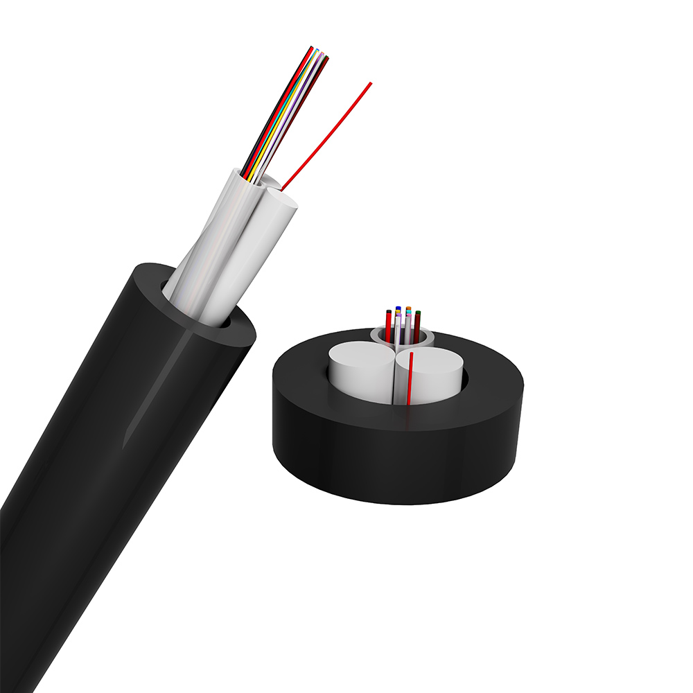
Bundle Tube Type all Dielectric ASU Self-Suppor...
The structure of the optical cable is designed to connect 250 μm optical fibers. The fibers are inserted into a loose tube made of high modulus material, which is then filled with waterproof compound. The loose tube and FRP are twisted together using SZ. Water blocking yarn is added to the cable core to prevent water seepage, and then a polyethylene (PE) sheath is extruded to form the cable. A stripping rope can be used to tear open the optical cable sheath. -

OYI-DIN-00 Series
DIN-00 is a DIN rail mounted fiber optic terminal box that used for fiber connection and distribution. It is made of aluminum, inside with plastic splice tray, light weight, good to use. -

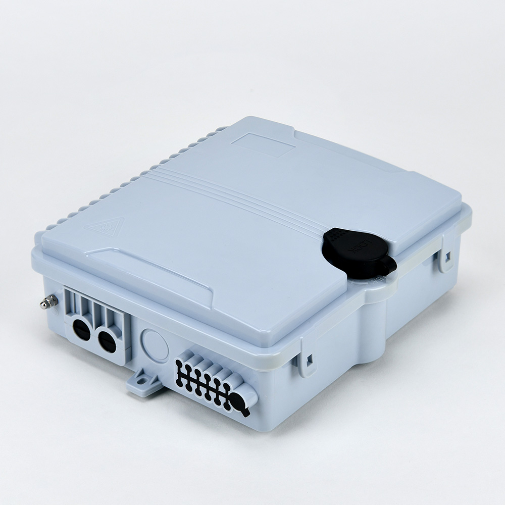
OYI-FAT-H16B4
Optical fiber distribution box 16 Cores fiber optic access termination box is able to hold up to 16 subscribers. It is used as a termination point for the feeder cable to connect with drop cable in FTTx network system. It integrates fiber splicing, splitting, distribution, storage and cable connection in one solid protection box. The optical distribution box is a solution that facilitates the installation of optical termination in branch networks for FTTH environments. -

GJFJKH
Jacketed aluminum interlocking armor provides the optimal balance of ruggedness, flexibility and low weight. The Multi-Strand Indoor Armored Tight-Buffered 10 Gig Plenum M OM3 Fiber Optic Cable from Discount Low Voltage is a good choice inside buildings where toughness is required or where rodents are a problem. These also are ideal for manufacturing plants and harsh industrial environments as well as high-density routings in data centers. Interlocking armor can be used with other types of cable, including indoor/outdoor tight-buffered cables. -
OYI-FAT12A Terminal Box
The 12-core OYI-FAT12A optical terminal box performs in accordance with the industry-standard requirements of YD/T2150-2010. It is mainly used in the FTTX access system terminal link. The box is made of high-strength PC, ABS plastic alloy injection molding, which provides good sealing and aging resistance. In addition, it can be hung on the wall outdoors or indoors for installation and use. -
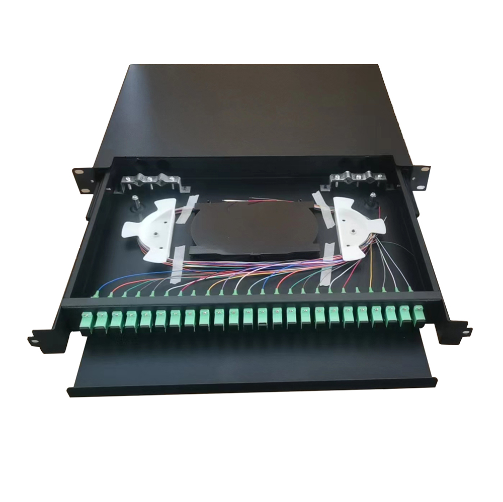
OYI-ODF-SR2-Series Type
OYI-ODF-SR2-Series Type optical fiber cable terminal panel is used for cable terminal connection, can be used as a distribution box. 19″ standard structure; Rack installation; Drawer structure design, with front cable management plate, Flexible pulling, Convenient to operate; Suitable for SC, LC ,ST, FC,E2000 adapters, etc. Rack mounted Optical Cable Terminal Box is the device that terminates between the optical cables and the optical communication equipments, with the function of splicing, termination, storing and patching of optical cables. SR-series sliding rail enclosure, easy access to fiber management and splicing. Aversatile solution in multiple sizes (1U/2U/3U/4U) and styles for building backbones, data centers and enterprise applications.
If you're looking for a reliable, high-speed fibre optic cable solution, look no further than OYI. Contact us now to see how we can help you stay connected and take your business to the next level.
