 0755-23179541
  sales@oyii.net
.png) 8618926041961
8618926041961
1.25Gbps 1550nm 60Km LC DDM
SFP Transceiver
1.25Gbps 1550nm 60Km LC DDM
Product Features
1. SFP package with LC connector.
2. 1550nm DFB laser and PIN photo detector.
3. Up to 60Km transmission on SMF.
4. +3.3V single power supply.
5. LVPECL compatible data input/output interface.
6. Low EMI and excellent ESD protection.
7. laser safety standard IEC-60825 compliant.
8. Compatible with RoHS.
9. Digital Diagnostic SFF-8472 compliant.
10. Signal Ground Isolated to Case.
Application
1. 1.25Gb/s 1000Base-LX Ethernet.
2. Dual Rate 1.06 / 2.125 Gb/s Fiber Channel.
Absolute Maximum Ratings:
|
Parameter |
Symbol |
Minimum |
Maximum |
Units |
|
Storage Temperature |
Tst |
-40 |
+85 |
℃ |
|
Supply Voltage |
Vcc |
0 |
+3.6 |
V |
|
Operating Relative Humidity |
RH |
5 |
95 |
% |
Operation Environment:
|
Parameter |
Symbol |
Min |
Typical |
Max |
Units |
|
Supply Voltage |
Vcc |
3.15 |
3.3 |
3.45 |
V |
|
Operating Case Temperature |
Tc |
0 |
|
+70 |
|
|
Power Dissipation |
|
|
|
1 |
W |
|
Data Rate |
|
|
1.25 |
|
Gbps |
Optical Characteristics
(Ambient Operating Temperature 0℃ to +70℃, Vcc =3.3 V)
|
Parameter |
Symbol |
Min. |
Typ. |
Max. |
Units |
|
Transmitter Section |
|||||
|
Center Wavelength |
λo |
1540 |
1550 |
1560 |
nm |
|
Spectral Width (RMS) |
△λ |
- |
- |
1 |
nm |
|
Average Output Power |
Po |
-5 |
- |
0 |
dBm |
|
Extinction Ratio |
Er |
8 |
- |
|
dB |
|
Rise/Fall Time (20%~80%) |
Tr/Tf |
|
|
180 |
ps |
|
Total jitter |
Tj |
|
|
0.43 |
UI |
|
Optical Eye Diagram |
IEEE 802.3z and ANSI Fiber Channel Compatible |
||||
|
Receiver Section |
|||||
|
Center Wavelength |
λo |
1260 |
|
1620 |
nm |
|
Receiver Sensitivity |
Rsen |
|
|
-24 |
dBm |
|
Receiver Overload |
Rov |
-3 |
|
|
dBm |
|
Return Loss |
|
12 |
|
|
dB |
|
LOS Assert |
LOSA |
-36 |
|
|
dBm |
|
LOS Dessert |
LOSD |
|
|
-25 |
dBm |
|
LOS Hysteresis |
|
0.5 |
|
5 |
|
Electrical Characteristics
(Ambient Operating Temperature 0℃ to +70℃, Vcc =3.3 V)
|
Parameter |
Symbol |
Min. |
Typ. |
Max. |
unit |
|
|
Transmitter Section |
||||||
|
Input Differential Impendence |
Zin |
90 |
100 |
110 |
Ohm |
|
|
Data Input Swing Differential |
Vin |
500 |
|
2400 |
mV |
|
|
TX Disable |
Disable |
|
2.0 |
|
Vcc |
V |
|
Enable |
|
0 |
|
0.8 |
V |
|
|
TX Fault |
Assert |
|
2.0 |
|
Vcc |
V |
|
Deassert |
|
0 |
|
0.8 |
V |
|
|
Receiver Section |
||||||
|
Output differential impendence |
Zout |
|
100 |
|
Ohm |
|
|
Data Input Swing Differential |
Vout |
370 |
|
2000 |
mV |
|
|
Rx_LOS |
Assert |
|
2.0 |
|
Vcc |
V |
|
Deassert |
|
0 |
|
0.8 |
V |
|
EEPROM INFORMATION(A0)
|
Addr |
Field Size (Bytes) |
Name of Field |
HEX |
Description |
|
0 |
1 |
Identifier |
03 |
SFP |
|
1 |
1 |
Ext. Identifier |
04 |
MOD4 |
|
2 |
1 |
Connector |
07 |
LC |
|
3-10 |
8 |
Transceiver |
00 00 00 02 12 00 0D 01 |
Transmitter Code |
|
11 |
1 |
Encoding |
01 |
8B10B |
|
12 |
1 |
BR, nominal |
0D |
1250M bps |
|
13 |
1 |
Reserved |
00 |
|
|
14 |
1 |
Length (9um)-km |
3C |
60km |
|
15 |
1 |
Length (9um) |
64/C8/FF |
|
|
16 |
1 |
Length (50um) |
00 |
|
|
17 |
1 |
Length (62.5um) |
00 |
|
|
18 |
1 |
Length (copper) |
00 |
|
|
19 |
1 |
Reserved |
00 |
|
|
20-35 |
16 |
Vendor name |
57 49 4E 54 4F 50 20 20 20 20 20 20 20 20 20 20 |
WINTOP |
|
36 |
1 |
Reserved |
00 |
|
|
37-39 |
3 |
Vendor OUI |
00 00 00 |
|
|
40-55 |
16 |
Vendor PN |
xx xx xx xx xx xx xx xx xx xx xx xx xx xx xx xx |
ASC II |
|
56-59 |
4 |
Vendor rev |
31 2E 30 20 |
V1.0 |
|
60-61 |
2 |
Wavelength |
06 0E |
1550nm |
|
62 |
1 |
Reserved |
00 |
|
|
63 |
1 |
CC BASE |
XX |
Check sum of byte 0~62 |
|
64-65 |
2 |
Options |
00 1A |
LOS, TX_DISABLE, TX_FAULT |
|
66 |
1 |
BR, max |
32 |
50% |
|
67 |
1 |
BR, min |
32 |
50% |
|
68-83 |
16 |
Vendor SN |
00 00 00 00 00 00 00 00 00 00 00 00 00 00 00 00 |
Unspecified |
|
84-91 |
8 |
Vendor date code |
XX XX XX 20 |
Year, Month, Day |
|
92-94 |
3 |
Reserved |
00 |
|
|
95 |
1 |
CC_EXT |
XX |
Check sum of byte 64~94 |
|
96-255 |
160 |
Vendor specific |
|
Diagnostics
|
Parameter |
Range |
Accuracy |
Unit |
Calibration |
|
Temperature |
0~70 |
±3 |
℃ |
Internal |
|
Voltage |
3.15~3.45 |
0.1 |
V |
Internal |
|
Bias Current |
10~80 |
±2 |
mA |
Internal |
|
Tx Power |
-6~1 |
±2 |
dBm |
Internal |
|
Rx Power |
-26~-3 |
±3 |
dBm |
Internal |
Pin Description
|
Pins |
Name |
Description |
NOTE |
|
1 |
VeeT |
Transmitter Ground |
|
|
2 |
Tx Fault |
Transmitter Fault Indication |
1 |
|
3 |
Tx Disable |
Transmitter Disable |
2 |
|
4 |
MOD DEF2 |
Module Definition 2 |
3 |
|
5 |
MOD DEF1 |
Module Definition 1 |
3 |
|
6 |
MOD DEF0 |
Module Definition 0 |
3 |
|
7 |
Rate Select |
Not Connected |
|
|
8 |
LOS |
Loss of Signal |
4 |
|
9 |
VeeR |
Receiver Ground |
|
|
10 |
VeeR |
Receiver Ground |
|
|
11 |
VeeR |
Receiver Ground |
|
|
12 |
RD- |
Inv. Received Data Output |
S |
|
13 |
RD+ |
IReceived Data Output |
S |
|
14 |
VeeR |
Receiver Ground |
|
|
15 |
VccR |
Receiver Power |
|
|
16 |
VccT |
Transmitter Power |
|
|
17 |
VeeT |
Transmitter Ground |
|
|
18 |
TD+ |
Transmit Data Input |
6 |
|
19 |
TD- |
Inv. Transmit Data Input |
6 |
|
20 |
VeeT |
Transmitter Ground |
Notes:
1. TX Fault is an open collector output, which should be pulled up with a 4.7k~10kΩ resistor on the host board to a voltage between 2.0V and Vcc+0.3V. Logic 0 indicates normal operation; logic 1 indicates a laser fault of some kind. In the low state, the output will be pulled to less than 0.8V.
2. TX Disable is an input that is used to shut down the transmitter optical output. It is pulled up with in the module with a 4.7k~10kΩ resistor. Its states are:
Low (0~0.8V): Transmitter on
(>0.8V, <2.0V): Undefined
High (2.0~3.3V): Transmitter Disabled
Open: Transmitter Disabled
3. MOD-DEF 0,1,2 are the module definition pins. They should be pulled up with a 4.7k~10kΩresistor on the host board. The pull-up voltage shall be VccT or VccR.
MOD-DEF 0 is grounded by the module to indicate that the module is present.
MOD-DEF 1 is the clock line of two wire serial interface for serial ID.
MOD-DEF 2 is the data line of two wire serial interface for serial ID.
4. LOS is an open collector output, which should be pulled up with a 4.7k~10kΩ resistor on the host board to a voltage between 2.0V and Vcc+0.3V. Logic 0 indicates normal operation; logic 1 indicates loss of signal. In the low state, the output will be pulled to less than 0.8V.
5. These are the differential receiver output. They are internally AC-coupled 100Ω differential lines which should be terminated with 100Ω (differential) at the user SERDES.
6. These are the differential transmitter inputs. They are AC-coupled, differential lines with 100Ω differential termination inside the module.
Recommended Application Circuit

Outline Dimensions (mm)

-
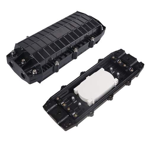
OYI-FOSC H12
The OYI-FOSC-04H Horizontal fiber optic splice closure has two connection ways: direct connection and splitting connection. They are applicable to situations such as overhead, manhole of pipeline, and embedded situations, etc. Comparing with a terminal box, the closure requires much stricter requirements for sealing. Optical splice closures are used to distribute, splice, and store the outdoor optical cables that enter and exit from the ends of the closure. The closure has 2 entrance ports and 2 output ports. The shell of the product is made from ABS/PC+PP material. These closures provide excellent protection for fiber optic joints from outdoor environments such as UV, water, and weather, with leak-proof sealing and IP68 protection. -
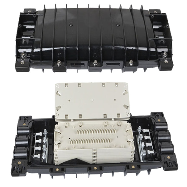
OYI-FOSC-H09
The OYI-FOSC-09H Horizontal fiber optic splice closure has two connection ways: direct connection and splitting connection. They are applicable to situations such as overhead, manhole of pipeline, and embedded situations, etc. Comparing with a terminal box, the closure requires much stricter requirements for sealing. Optical splice closures are used to distribute, splice, and store the outdoor optical cables that enter and exit from the ends of the closure. The closure has 3 entrance ports and 3 output ports. The shell of the product is made from PC+PP material. These closures provide excellent protection for fiber optic joints from outdoor environments such as UV, water, and weather, with leak-proof sealing and IP68 protection. -

OYI-NOO1 Floor-Mounted Cabinet
Frame: Welded frame, stable structure with precise craftsmanship. -
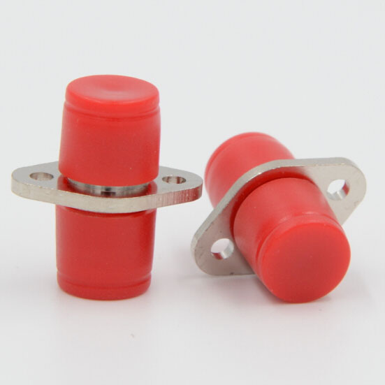
FC Type
Fiber optic adapter, sometimes also called a coupler, is a small device designed to terminate or link fiber optic cables or fiber optic connectors between two fiber optic lines. It contains the interconnect sleeve that holds two ferrules together. By precisely linking two connectors, fiber optic adapters allow the light sources to be transmitted at their maximum and minimize the loss as much as possible. At the same time, fiber optic adapters have the advantages of low insertion loss, good interchangeability, and reproducibility. They are used to connect optical fiber connectors such as FC, SC, LC, ST, MU, MTRJ, D4, DIN, MPO, etc. They are widely used in optical fiber communications equipment, measuring appliances, and so on. The performance is stable and reliable. -

10/100Base-TX Ethernet Port to 100Base-FX Fiber...
MC0101G fiber Ethernet media converter creates a cost-effective Ethernet to fiber link, transparently converting to/from 10Base-T or 100Base-TX or 1000Base-TX Ethernet signals and 1000Base-FX fiber optical signals to extend an Ethernet network connection over a multimode/single mode fiber backbone.MC0101G fiber Ethernet media converter supports maximum multimode fiber optic cable distance of 550m or a maximum single mode fiber optic cable distance of 120km providing a simple solution for connecting 10/100Base-TX Ethernet networks to remote locations using SC/ST/FC/LC terminated single mode/multimode fiber, while delivering solid network performance and scalability.Easy to set-up and install, this compact, value-conscious fast Ethernet media converter features auto. switching MDI and MDI-X support on the RJ45 UTP connections as well as manual controls for UTP mode speed, full and half duplex. -

OYI 3436G4R
ONU product is the terminal equipment of a series of XPON which comply fully with ITU-G.984.1/2/3/4 standard and meet the energy-saving of G.987.3 protocol, ONU is based on mature and stable and high cost-effective GPON technology which adopts high-performance XPON REALTEK chipset and has high reliability, easy management, flexible configuration,robustness,good quality service guarantee(Qos). This ONU supports IEEE802.11b/g/n/ac/ax, called WIFI6, concurrently, a WEB system provided simplifi es the configuration of the WIFI and connects to INTERNET conveniently for users. The ONU supports one pots for VOIP application.
If you're looking for a reliable, high-speed fibre optic cable solution, look no further than OYI. Contact us now to see how we can help you stay connected and take your business to the next level.
