
 0755-23179541
  sales@oyii.net
.png) 8618926041961
8618926041961
SFP+ 80km Transceiver
10Gb/s BIDl 1550/1490nm
SFP+ 80km Transceiver
Product Description
PPB-5496-80B is hot pluggable 3.3V Small-Form-Factor transceiver module. It designed expressly for high-speed communication applications that require rates up to 11.1Gbps, it designed to be compliant with SFF-8472 and SFP+ MSA. The module data link up to 80km in 9/125um single mode fiber.
Product Features
1. Up to 11.1Gbps Data Links.
2. Up to 80km transmission on SMF.
3. Power dissipation<1.5W.
4. 1490nm DFB laser and APD receiver for FYPPB-4596-80B.
1550nm DFB laser and APD receiver for FYPPB-5496-80B
5. 6.2-wire interface with integrated Digital Diagnostic monitoring.
6. EEPROM with Serial ID Functionality.
7. Hot-pluggable SFP+ footprint.
8. Compliant with SFP+ MSA with LC connector.
9. Single + 3.3V Power Supply.
10. Case operating temperature: 0ºC ~+70ºC.
Applications
1.10GBASE-BX.
2.10GBASE-LR/LW.
Standard
1.Compliant with SFF-8472.
2.Compliant to SFF-8431.
3.Compliant to 802.3ae 10GBASE-LR/LW.
4.RoHS Compliant.
Pin Descriptions
|
Pin |
Symbol |
Name/Description |
NOTE |
|
1 |
VEET |
Transmitter Ground (Common with Receiver Ground) |
1 |
|
2 |
TFAULT |
Transmitter Fault. |
2 |
|
3 |
TDIS |
Transmitter Disable. Laser output disabled on high or open. |
3 |
|
4 |
MOD_DEF (2) |
Module Definition 2. Data line for Serial ID. |
4 |
|
5 |
MOD_DEF (1) |
Module Definition 1. Clock line for Serial ID. |
4 |
|
6 |
MOD_DEF (0) |
Module Definition 0. Grounded within the module. |
4 |
|
7 |
Rate Select |
No connection required |
5 |
|
8 |
LOS |
Loss of Signal indication. Logic 0 indicates normal operation. |
6 |
|
9 |
VEER |
Receiver Ground (Common with Transmitter Ground) |
1 |
|
10 |
VEER |
Receiver Ground (Common with Transmitter Ground) |
1 |
|
11 |
VEER |
Receiver Ground (Common with Transmitter Ground) |
1 |
|
12 |
RD- |
Receiver Inverted DATA out. AC Coupled |
|
|
13 |
RD+ |
Receiver Non-inverted DATA out. AC Coupled |
|
|
14 |
VEER |
Receiver Ground (Common with Transmitter Ground) |
1 |
|
15 |
VCCR |
Receiver Power Supply |
|
|
16 |
VCCT |
Transmitter Power Supply |
|
|
17 |
VEET |
Transmitter Ground (Common with Receiver Ground) |
1 |
|
18 |
TD+ |
Transmitter Non-Inverted DATA in. AC Coupled. |
|
|
19 |
TD- |
Transmitter Inverted DATA in. AC Coupled. |
|
|
20 |
VEET |
Transmitter Ground (Common with Receiver Ground) |
1 |
Notes:
1.Circuit ground is internally isolated from chassis ground.
2.TFAULT is an open collector/drain output, which should be pulled up with a 4.7k – 10k Ohms resistor on the host board if intended for use. Pull up voltage should be between 2.0V to Vcc + 0.3V.A high output indicates a transmitter fault caused by either the TX bias current or the TX output power exceeding the preset alarm thresholds. A low output indicates normal operation. In the low state, the output is pulled to <0.8V.
3.Laser output disabled on TDIS >2.0V or open, enabled on TDIS <0.8V.
4.Should be pulled up with 4.7kΩ- 10kΩ host board to a voltage between 2.0V and 3.6V. MOD_ABS pulls line low to indicate module is plugged in.
5.Internally pulled down per SFF-8431 Rev 4.1.
6.LOS is open collector output. It should be pulled up with 4.7kΩ – 10kΩ on host board to a voltage between 2.0V and 3.6V. Logic 0 indicates normal operation; logic 1 indicates loss of signal.
Pin Diagram

Absolute Maximum Ratings
|
Parameter |
Symbol |
Min. |
Typ. |
Max. |
Unit |
Note |
|
Storage Temperature |
Ts |
-40 |
|
85 |
ºC |
|
|
Relative Humidity |
RH |
5 |
|
95 |
% |
|
|
Power Supply Voltage |
VCC |
-0.3 |
|
4 |
V |
|
|
Signal Input Voltage |
|
Vcc-0.3 |
|
Vcc+0.3 |
V |
Recommended Operating Conditions
|
Parameter |
Symbol |
Min. |
Typ. |
Max. |
Unit |
Note |
|
Case Operating Temperature |
Tcase |
0 |
|
70 |
ºC |
Without air flow |
|
Power Supply Voltage |
VCC |
3.13 |
3.3 |
3.47 |
V |
|
|
Power Supply Current |
ICC |
|
|
520 |
mA |
|
|
Data Rate |
|
|
10.3125 |
|
Gbps |
TX Rate/RX Rate |
|
Transmission Distance |
|
|
|
80 |
KM |
|
|
Coupled Fiber |
|
|
Single mode fiber |
|
9/125um SMF |
|
Optical Characteristics
|
Parameter |
Symbol |
Min. |
Typ. |
Max. |
Unit |
Note |
|
|
Transmitter |
|
|
|
||
|
Average Launched Power |
POut |
0 |
- |
5 |
dBm |
|
|
Average Launched Power (Laser Off) |
Poff |
- |
- |
-30 |
dBm |
Note (1) |
|
Center Wavelength Range |
λC |
1540 |
1550 |
1560 |
nm |
FYPPB-5496-80B |
|
Side mode suppression ratio |
SMSR |
30 |
- |
- |
dB |
|
|
Spectrum Bandwidth(-20dB) |
σ |
- |
- |
1 |
nm |
|
|
Extinction Ratio |
ER |
3.5 |
|
- |
dB |
Note (2) |
|
Output Eye Mask |
Compliant with IEEE 802.3ae |
|
|
Note (2) |
||
|
|
Receiver |
|
|
|
||
|
Input Optical Wavelength |
λIN |
1480 |
1490 |
1500 |
nm |
FYPPB-5496-80B |
|
Receiver Sensitivity |
Psen |
- |
- |
-23 |
dBm |
Note (3) |
|
Input Saturation Power (Overload) |
PSAT |
-8 |
- |
- |
dBm |
Note (3) |
|
LOS -Assert Power |
PA |
-38 |
- |
- |
dBm |
|
|
LOS -Deassert Power |
PD |
- |
- |
-24 |
dBm |
|
|
LOS -Hysteresis |
PHys |
0.5 |
- |
5 |
dB |
|
Note:
1.The optical power is launched into SMF
2.Measured with RPBS 2^31-1 test pattern @10.3125Gbs
3.Measured with RPBS 2^31-1 test pattern @10.3125Gbs BER=<10^-12
Electrical Interface Characteristics
|
Parameter |
Symbol |
Min. |
Typ. |
Max. |
Unit |
Note |
|
Total power supply current |
Icc |
- |
|
520 |
mA |
|
|
Transmitter |
||||||
|
Differential Data Input Voltage |
VDT |
180 |
- |
700 |
mVp-p |
|
|
Differential line input Impedance |
RIN |
85 |
100 |
115 |
Ohm |
|
|
Transmitter Fault Output-High |
VFaultH |
2.4 |
- |
Vcc |
V |
|
|
Transmitter Fault Output-Low |
VFaultL |
-0.3 |
- |
0.8 |
V |
|
|
Transmitter Disable Voltage- High |
VDisH |
2 |
- |
Vcc+0.3 |
V |
|
|
Transmitter Disable Voltage- low |
VDisL |
-0.3 |
- |
0.8 |
V |
|
|
Receiver |
||||||
|
Differential Data Output Voltage |
VDR |
300 |
- |
850 |
mVp-p |
|
|
Differential line Output Impedance |
ROUT |
80 |
100 |
120 |
Ohm |
|
|
Receiver LOS Pull up Resistor |
RLOS |
4.7 |
- |
10 |
KOhm |
|
|
Data Output Rise/Fall time |
tr/tf |
|
- |
38 |
ps |
|
|
LOS Output Voltage-High |
VLOSH |
2 |
- |
Vcc |
V |
|
|
LOS Output Voltage-Low |
VLOSL |
-0.3 |
- |
0.4 |
V |
|
Digital Diagnostic Functions
PPB-5496-80B transceivers support the 2-wire serial communication protocol as defined in the SFP+MSA.
The standard SFP serial ID provides access to identification information that describes the transceiver’s capabilities, standard interfaces, manufacturer, and other information.
Additionally, OYI’s SFP+ transceivers provide a unique enhanced digital diagnostic monitoring interface, which allows real-time access to device operating parameters such as transceiver temperature, laser bias current, transmitted optical power, received optical power and transceiver supply voltage. It also defines a sophisticated system of alarm and warning flags, which alerts end-users when particular operating parameters are outside of a factory set normal range.
The SFP MSA defines a 256-byte memory map in EEPROM that is accessible over a 2-wire serial interface at the 8 bit address 1010000X (A0h).The digital diagnostic monitoring interface makes use of the 8 bit address 1010001X (A2h), so the originally defined serial ID memory map remains unchanged.
The operating and diagnostics information is monitored and reported by a Digital Diagnostics Transceiver Controller (DDTC) inside the transceiver, which is accessed through a 2-wire serial interface. When the serial protocol is activated, the serial clock signal (SCL, Mod Def 1) is generated by the host. The positive edge clocks data into the SFP transceiver into those segments of the E2PROM that are not write-protected. The negative edge clocks data from the SFP transceiver. The serial data signal (SDA, Mod Def 2) is bi-directional for serial data transfer. The host uses SDA in conjunction with SCL to mark the start and end of serial protocol activation.
The memories are organized as a series of 8-bit data words that can be addressed individually or sequentially.
Recommend Circuit Schematic

Mechanical Specifications (Unit: mm)

Regulatory Compliance
|
Feature |
Reference |
Performance |
|
Electrostatic discharge(ESD) |
IEC/EN 61000-4-2 |
Compatible with standards |
|
Electromagnetic Interference (EMI) |
FCC Part 15 Class B EN 55022 Class B (CISPR 22A) |
Compatible with standards |
|
Laser Eye Safety |
FDA 21CFR 1040.10, 1040.11 IEC/EN 60825-1,2 |
Class 1 laser product |
|
Component Recognition |
IEC/EN 60950 ,UL |
Compatible with standards |
|
ROHS |
2002/95/EC |
Compatible with standards |
|
EMC |
EN61000-3 |
Compatible with standards |
-

SFP-ETRx-4
OPT-ETRx-4 Copper Small Form Pluggable (SFP) transceivers are based on the SFP Multi Source Agreement (MSA). They are compatible with the Gigabit Ethernet standards as specified in IEEE STD 802.3. The 10/100/1000 BASE-T physical layer IC (PHY) can be accessed via 12C, allowing access to all PHY settings and features. The OPT-ETRx-4 is compatible with 1000BASE-X auto-negotiation, and have a link indication feature. PHY is disabled when TX disable is high or open. -

OYI-DIN-FB Series
Fiber optic Din terminal box is available for the distribution and terminal connection for various kinds of optical fiber system, especially suitable for mini-network terminal distribution, in which the optical cables, patch cores or pigtails are connected. -

OYI-FTB-10A Terminal Box
The equipment is used as a termination point for the feeder cable to connect with drop cable in FTTx communication network system. The fiber splicing, splitting, distribution can be done in this box, and meanwhile it provides solid protection and management for the FTTx network building. -
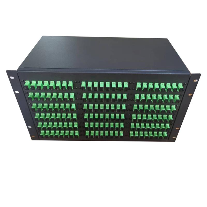
OYI-ODF-FR-Series Type
The OYI-ODF-FR-Series type optical fiber cable terminal panel is used for cable terminal connection and can also be used as a distribution box. It has a 19″ standard structure and is of the fixed rack-mounted type, making it convenient to operate. It is suitable for SC, LC, ST, FC, E2000 adapters, and more. The rack mounted optical cable terminal box is a device that terminates between the optical cables and the optical communication equipment. It has the functions of splicing, termination, storing, and patching of optical cables. The FR-series rack mount fiber enclosure provides easy access to fiber management and splicing. It offers a versatile solution in multiple sizes (1U/2U/3U/4U) and styles for building backbones, data centers, and enterprise applications. -
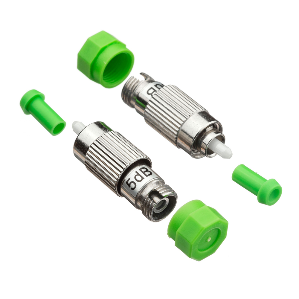
Male to Female Type FC Attenuator
OYI FC male-female attenuator plug type fixed attenuator family offers high performance of various fixed attenuation for industrial standard connections. It has a wide attenuation range, extremely low return loss, is polarization insensitive, and has excellent repeatability. With our highly integrated design and manufacturing capability, the attenuation of male-female type SC attenuator can also be customized to help our customers find better opportunities. Our attenuator complies with industry green initiatives, such as ROHS. -
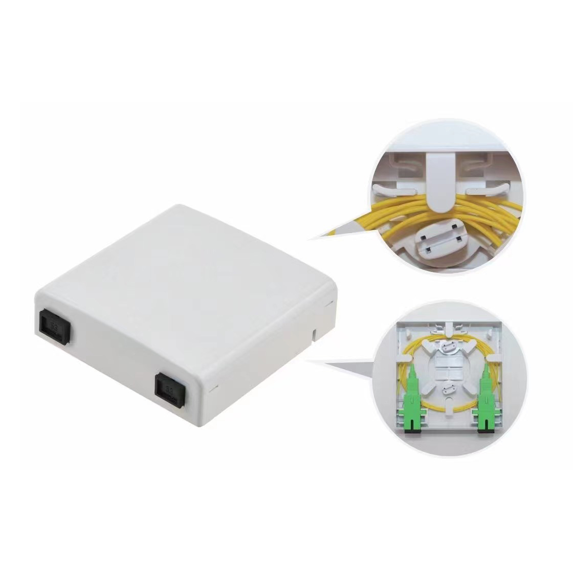
OYI-ATB02A Desktop Box
OYI-ATB02A 86 double-port desktop box is developed and produced by the company itself. The product’s performance meets the requirements of industry standards YD/T2150-2010. It is suitable for installing multiple types of modules and can be applied to the work area wiring subsystem to achieve dual-core fiber access and port output. It provides fiber fixing, stripping, splicing, and protection devices, and allows for a small amount of redundant fiber inventory, making it suitable for FTTD (fiber to the desktop) system applications. The box is made of high-quality ABS plastic through injection molding, making it anti-collision, flame retardant, and highly impact-resistant. It has good sealing and anti-aging properties, protecting the cable exit and serving as a screen. It can be installed on the wall.
If you're looking for a reliable, high-speed fibre optic cable solution, look no further than OYI. Contact us now to see how we can help you stay connected and take your business to the next level.
