 0755-23179541
  sales@oyii.net
.png) 8618926041961
8618926041961
Armored Optic Cable GYFXTS
Armored Optic Cable
GYFXTS
Product Features
1. Small size and light weight, with good bending resistance performance easy to installation.
2. High strength loose tube material with good performance of hydrolysis resistant, special tube filling compound ensure a critical protection of fiber.
3. Full section filled, cable core wrapped longitudinally with corrugated steel plastic tape enhancing moisture-proof.
4. Cable core wrapped longitudinally with corrugated steel plastic tape enhancing crush resistance.
5. All selection water blocking construction, provide good performance of moisture-proof and water block.
6. Special filling gel filled loose tubes provide perfect optical fiber protection.
7. Strict craft and raw material control enable lifespan over 30 years.
Specification
The cables are mainly designed for digital or analog transmission communication and rural communication system. The products are suitable for aerial installation, tunnel installation or direct buried.
|
ITEMS |
DESCRIPTION |
||
|
Fiber Count |
2 ~ 16F |
24F |
|
|
Loose Tube |
OD(mm): |
2.0 ± 0.1 |
2.5± 0.1 |
|
Material: |
PBT |
||
|
Armored |
Corrugation Steel tape |
||
|
Sheath |
Thickness: |
Non. 1.5 ± 0.2 mm |
|
|
Material: |
PE |
||
|
OD of cable (mm) |
6.8 ± 0.4 |
7.2 ± 0.4 |
|
|
Net weight ( kg/km) |
70 |
75 |
|
Specification
FIBER IDENTIFICATION
|
NO. |
1 |
2 |
3 |
4 |
5 |
6 |
7 |
8 |
9 |
10 |
11 |
12 |
|
Tube Color |
Blue |
Orange |
Green |
Brown |
Slate |
White |
Red |
Black |
Yellow |
Violet |
Pink |
Aqua |
|
NO. |
1 |
2 |
3 |
4 |
5 |
6 |
7 |
8 |
9 |
10 |
11 |
12 |
|
Fiber Color
NO.
Fiber Color |
Blue |
Orange |
Green |
Brown |
Slate |
White/ natural |
Red |
Black |
Yellow |
Violet |
Pink |
Aqua |
|
13. |
14 |
15 |
16 |
17 |
18 |
19 |
20 |
21 |
22 |
23 |
24 |
|
|
Blue +Black point |
Orange+ Black point |
Green+ Black point |
Brown+ Black point |
Slate+B lack point |
White+ Black point |
Red+ Black point |
Black+ White point |
Yellow+ Black point |
Violet+ Black point |
Pink+ Black point |
Aqua+ Black point |
OPTICAL FIBER
1.Single Mode Fiber
|
ITEMS |
UNITS |
SPECIFICATION |
|
Fiber type |
|
G652D |
|
Attenuation |
dB/km |
1310 nm≤ 0.36 1550 nm≤ 0.22 |
|
Chromatic Dispersion |
ps/nm.km |
1310 nm≤ 3.5 1550 nm≤ 18 1625 nm≤ 22 |
|
Zero Dispersion Slope |
ps/nm2.km |
≤ 0.092 |
|
Zero Dispersion Wavelength |
nm |
1300 ~ 1324 |
|
Cut-off Wavelength (lcc) |
nm |
≤ 1260 |
|
Attenuation vs. Bending (60mm x100turns) |
dB |
(30 mm radius,100 rings )≤ 0.1 @ 1625 nm |
|
Mode Field Diameter |
mm |
9.2 ± 0.4 at 1310 nm |
|
Core-Clad Concentricity |
mm |
≤ 0.5 |
|
Cladding Diameter |
mm |
125 ± 1 |
|
Cladding Non-circularity |
% |
≤ 0.8 |
|
Coating Diameter |
mm |
245 ± 5 |
|
Proof Test |
Gpa |
≥ 0.69 |
2.Multi Mode Fiber
|
ITEMS |
UNITS |
SPECIFICATION |
|||||||
|
62.5/125 |
50/125 |
OM3-150 |
OM3-300 |
OM4-550 |
|||||
|
Fiber Core Diameter |
μm |
62.5 ± 2.5 |
50.0 ± 2.5 |
50.0 ± 2.5 |
|||||
|
Fiber Core Non-circularity |
% |
≤ 6.0 |
≤ 6.0 |
≤ 6.0 |
|||||
|
Cladding Diameter |
μm |
125.0 ± 1.0 |
125.0 ± 1.0 |
125.0 ± 1.0 |
|||||
|
Cladding Non-circularity |
% |
≤ 2.0 |
≤2.0 |
≤ 2.0 |
|||||
|
Coating Diameter |
μm |
245 ± 10 |
245 ± 10 |
245 ± 10 |
|||||
|
Coat-Clad Concentricity |
μm |
≤ 12.0 |
≤ 12.0 |
≤12.0 |
|||||
|
Coating Non-circularity |
% |
≤ 8.0 |
≤ 8.0 |
≤ 8.0 |
|||||
|
Core-Clad Concentricity |
μm |
≤ 1.5 |
≤ 1.5 |
≤ 1.5 |
|||||
|
Attenuation |
850nm |
dB/km |
3.0 |
3.0 |
3.0 |
||||
|
1300nm |
dB/km |
1.5 |
1.5 |
1.5 |
|||||
|
OFL |
850nm |
MHz﹒ km |
≥ 160 |
≥ 200 |
≥ 700 |
≥ 1500 |
≥ 3500 |
||
|
1300nm |
MHz﹒ km |
≥ 300 |
≥ 400 |
≥ 500 |
≥ 500 |
≥ 500 |
|||
|
The biggest theory numerical aperture |
/ |
0.275 ± 0.015 |
0.200 ± 0.015 |
0.200 ± 0.015 |
|||||
Mechanical and Environmental Performance of the Cable
|
NO. |
ITEMS |
TEST METHOD |
ACCEPTANCE CRITERIA |
|
1 |
Tensile Loading Test |
#Test method: IEC 60794-1-E1 -. Long-tensile load: 500 N -. Short-tensile load: 1000 N -. Cable length: ≥ 50 m |
-. Attenuation increment@1550 nm: ≤ 0.1 dB -. No jacket cracking and fiber breakage |
|
2 |
Crush Resistance Test |
#Test method: IEC 60794-1-E3 -.Long load: 1000 N/100mm -.Short load: 2000 N/100mm Load time: 1 minutes |
-. Attenuation increment@1550 nm: ≤ 0.1 dB -. No jacket cracking and fiber breakage |
|
3 |
Impact Resistance Test |
#Test method: IEC 60794-1-E4 -.Impact height: 1 m -.Impact weigh: 450 g -.Impact point: ≥ 5 -.Impact frequency: ≥ 3/point |
-. Attenuation increment@1550 nm: ≤ 0.1 dB -. No jacket cracking and fiber breakage |
|
4 |
Repeated Bending |
#Test method: IEC 60794-1-E6 -.Mandrel diameter: 20 D (D = cable diameter) -.Subject weight: 15 kg -.Bending frequency: 30 times -.Bending speed: 2 s/time |
-. Attenuation increment@1550 nm: ≤ 0.1 dB -. No jacket cracking and fiber breakage |
|
5 |
Torsion Test |
#Test method: IEC 60794-1-E7 -.Length: 1 m -.Subject weight: 25 kg -.Angle: ± 180 degree -.Frequency: ≥ 10/point |
-. Attenuation increment@1550 nm: ≤0.1 dB -. No jacket cracking and fiber breakage |
|
6 |
Water Penetration Test |
#Test method: IEC 60794-1-F5B -.Height of pressure head: 1 m -.Length of specimen: 3 m -.Test time: 24 hours |
-. No leakage through the open cable end |
|
7 |
Temperature Cycling Test |
#Test method: IEC 60794-1-F1 -.Temperature steps: + 20℃,- 40℃,+ 70℃,+ 20℃ -.Testing Time: 24 hours/step -.Cycle index: 2 |
-. Attenuation increment@1550 nm: ≤ 0.1 dB -. No jacket cracking and fiber breakage |
|
8 |
Drop Performance |
#Test method: IEC 60794-1-E14 -.Testing length: 30 cm -.Temperature range: 70 ±2℃ -.Testing Time: 24 hours |
-. No filling compound drop out |
|
9 |
Temperature |
Operating: -40℃~+70℃ Store/Transport: -40℃~+70℃ Installation: -20℃~+60℃ |
|
FIBER OPTIC CABLE BENDING RADIUS
Static bending: ≥ 10 times than cable out diameter
Dynamic bending: ≥ 20 times than cable out diameter.
PACKAGE AND MARK
1.Package
Not allowed two length units of cable in one drum, two ends should be sealed, Two ends should be packed inside drum, reserve length of cable not less than 3 meters.

2.Mark
Cable Mark: Brand, Cable type, Fiber type and counts, Year of manufacture, Length marking.
TEST REPORT
Test report and certification will be supplied on demand.
-

GPON OLT Series Datasheet
GPON OLT 4/8PON is highly integrated, medium-capacity GPON OLT for operators, ISPS, enterprises and park-applications. The product follows the ITU-T G.984/G.988 technical standard,The product has good openness, strong compatibility, high reliability, and complete software functions. It can be widely used in operators’ FTTH access, VPN, government and enterprise park access, campus network access, ETC.GPON OLT 4/8PON is only 1U in height, easy to install and maintain, and save space. Supports mixed networking of different types of ONU, which can save a lot of costs for operators. -
3213GER
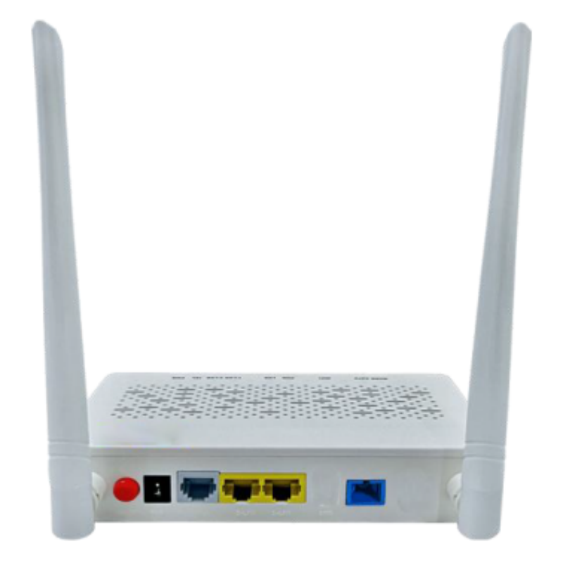
ONU product is the terminal equipment of a series of XPON which comply fully with ITU-G.984.1/2/3/4 standard and meet the energy-saving of G.987.3 protocol, ONU is based on mature and stable and high cost-effective GPON technology which adopts high-performance XPON Realtek chip set and has high reliability, easy management,flexible configuration,robustness,good quality service guarantee(Qos).ONU adopts RTL for WIFI application that supports IEEE802.11b/g/n standard at the same time,a WEB system provided simplifies the configuration of the ONU and connects to INTERNET conveniently for users.XPON has G / E PON mutual conversion function, which is realized by pure software.ONU support one pots for VOIP application. -
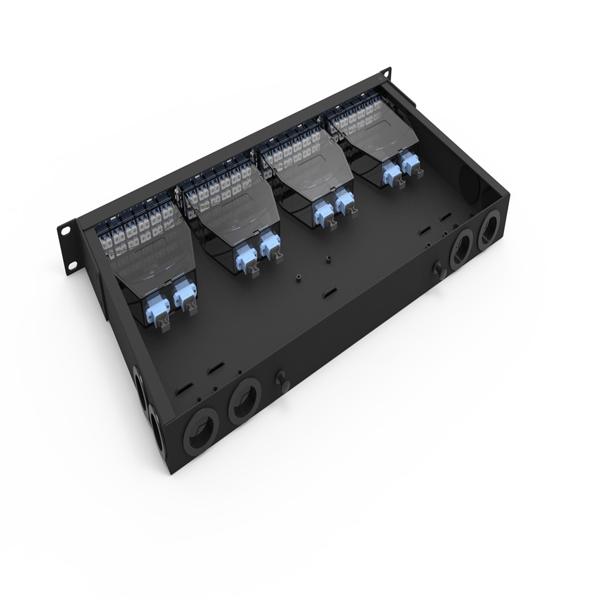
OYI-ODF-MPO-Series Type
The rack mount fiber optic MPO patch panel is used for cable terminal connection, protection, and management on trunk cable and fiber optic. It is popular in data centers, MDA, HAD, and EDA for cable connection and management. It is installed in a 19-inch rack and cabinet with an MPO module or MPO adapter panel. It has two types: fixed rack mounted type and drawer structure sliding rail type. It can also be widely used in optical fiber communication systems, cable television systems, LANs, WANs, and FTTX. It is made with cold rolled steel with Electrostatic spray, providing strong adhesive force, artistic design, and durability. -

OYI-F235-16Core
This box is used as a termination point for the feeder cable to connect with drop cable in FTTX communication network system. It intergtates fiber splicing, splitting, distribution, storage and cable connection in one unit. Meanwhile, it provides solid protection and management for the FTTX network building. -

OYI-OW2 series Type
Outdoor Wall-mount Fiber Optic Distribution Frame is mainly used for connecting the outdoor optical cables, optical patch cords and optical pigtails. It can be wall mounted or pole mounted, and facilitates the test and refit of the lines. It is an integrated unit for fiber management, and can be used as distribution box. This equipment function is to fix and manage the fiber optic cables inside the box as well as provide protection. Fiber optic termination box is modular so they are applying cable to your existing systems without any modification or additional work. Suitable for installation of FC, SC, ST, LC, etc. adaptors, and suitable for fiber optic pigtail or plastic box type PLC splitters and large working space to integrate the pigtails, cables and adapters. -
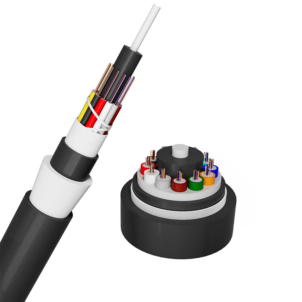
Loose Tube Non-metallic Heavy Type Rodent Prote...
Insert the optical fiber into the PBT loose tube, fill the loose tube with waterproof ointment. The center of the cable core is a non-metallic reinforced core, and the gap is filled with waterproof ointment. The loose tube (and filler) is twisted around the center to strengthen the core, forming a compact and circular cable core. A layer of protective material is extruded outside the cable core, and glass yarn is placed outside the protective tube as a rodent proof material. Then, a layer of polyethylene (PE) protective material is extruded.(WITH DOUBLE SHEATHS)
If you're looking for a reliable, high-speed fibre optic cable solution, look no further than OYI. Contact us now to see how we can help you stay connected and take your business to the next level.
