 0755-23179541
  sales@oyii.net
.png) 8618926041961
8618926041961
SFP-ETRx-4
10/100/1000 BASE-T Copper SFP Transceiver
SFP-ETRx-4
Product Features
1.Up to 1.25 Gb/s bi-directional data links.
2.Link lengths at 1.25 Gb/s up to 100 meters.
3.10/100/1000 BASE-T operation in host systems with SGMII interface.
4.Support TX- disable and Link function.
5.Compliant with SFP MSA.
6.Compact RJ-45 connector assembly.
7.Hot-pluggable SFP Footprint.
8.Single + 3.3V Power Supply.
9.Fully Metallic Enclosure for Low EMI.
10.Low power dissipation (1.05W typical).
11.RoHS compliant and lead-free.
12.Operating case temperature Commercial: 0 ~ +70oC.
Extended: -10 ~ +80oC.
Industrial: -40 ~ +85oC.
Technical Specifications
1.LAN 1000Base-T.
2.Switch to Switch Interface.
3.Router/Server interface.
4.witched backplane applications.
|
Part Number |
Data Rate (Mb/s) |
Transmission Distance(m) |
Link Indicator on RX-LOS pin |
TX-disable with PHY |
Temperature (oC) (Operating Case) |
|
OPT-ETRC-4 |
10/100/1000 |
100 |
Yes |
Yes |
0~70 commercial |
|
OPT-ETRE-4 |
10/100/1000 |
100 |
Yes |
Yes |
-10~80 Extended |
|
OPT-ETRI-4 |
10/100/1000 |
100 |
Yes |
Yes |
-40~85 Industrial |
1. Absolute Maximum Ratings
It has to be noted that the operation in excess of any individual absolute maximum ratings might cause permanent damage to this module.
|
Parameter |
Symbol |
Min |
Max |
Unit |
Notes |
|
Storage Temperature |
TS |
-40 |
85 |
oC |
|
|
Power Supply Voltage |
VCC |
-0.5 |
3.6 |
V |
|
|
Relative Humidity (non-condensation) |
RH |
5 |
95 |
% |
2.Recommended Operating Conditions and Power Supply Requirements
| Parameter | Symbol | Min | Typical | Max | Unit | Notes |
| Operating Case Temperature | TOP | 0 | 70 | oC | commercial | |
| -10 | 80 | extended | ||||
| -40 | 85 | industrial | ||||
| Power Supply Voltage | VCC | 3.135 | 3.3 | 3.465 | V | |
| Data Rate | 10 | 1000 | Mb/s | |||
| Link Distance (SMF) | D | 100 | m |
3. Pin Assignment and Pin Description

Figure1. Diagram of host board connector block pin numbers and names.
|
PIN |
Name |
Name/Description |
Notes |
|
1 |
VEET |
Transmitter Ground (Common with Receiver Ground) |
1 |
|
2 |
TXFAULT |
Transmitter Fault. |
|
|
3 |
TXDIS |
Transmitter Disable. Laser output disabled on high or open. |
|
|
4 |
MOD-DEF (2) |
Module Definition 2. Data line for Serial ID. |
2 |
|
5 |
MOD-DEF (1) |
Module Definition 1. Clock line for Serial ID. |
2 |
|
6 |
MOD-DEF (0) |
Module Definition 0. Grounded within the module. |
2 |
|
7 |
Rate Select |
No connection required |
|
|
8 |
LOS |
Loss of Signal indication. Logic 0 indicates normal operation. |
3 |
|
9 |
VEER |
Receiver Ground (Common with Transmitter Ground) |
1 |
|
10 |
VEER |
Receiver Ground (Common with Transmitter Ground) |
1 |
|
11 |
VEER |
Receiver Ground (Common with Transmitter Ground) |
1 |
|
12 |
RD- |
Receiver Inverted DATA out. AC Coupled |
|
|
13 |
RD+ |
Receiver Non-inverted DATA out. AC Coupled |
|
|
14 |
VEER |
Receiver Ground (Common with Transmitter Ground) |
1 |
|
15 |
VCCR |
Receiver Power Supply |
|
|
16 |
VCCT |
Transmitter Power Supply |
|
|
17 |
VEET |
Transmitter Ground (Common with Receiver Ground) |
1 |
|
18 |
TD+ |
Transmitter Non-Inverted DATA in. AC Coupled. |
|
|
19 |
TD- |
Transmitter Inverted DATA in. AC Coupled. |
|
|
20 |
VEET |
Transmitter Ground (Common with Receiver Ground) |
1 |
Notes:
1.Circuit ground is connected to chassis ground.
2.Should be pulled up with 4.7k - 10k Ohms on host board to a voltage between 2.0 V and 3.6 V.
MOD-DEF (0) pulls line low to indicate module is plugged in.
3.LVTTL compatible with a maximum voltage of 2.5V.
4. Power Supply Interface Electronic Characteristics
The OPT-ETRx-4 has an input voltage range of 3.3 V ± 5%. The 4 V maximum voltage is not allowed for continuous operation.
|
Parameter |
Symbol |
Min |
Typical |
Max |
Unit |
Notes |
|
Power Consumption |
|
|
|
1.2 |
W |
|
|
Supply Current |
Icc |
|
|
375 |
mA |
|
|
Input Voltage Tolerance |
|
-0.3 |
|
4.0 |
V |
|
|
Surge |
Surge |
|
30 |
|
mV |
|
|
Current |
|
current See caution note |
|
|||
Notes: Power consumption and surge current are higher than the specified values in the SFP MSA.
5. Low-Speed Signals Electronic Characteristics
MOD-DEF (1) (SCL) and MOD-DEF (2) (SDA) are open drain CMOS signals. Both MOD-DEF (1) and MOD-DEF (2) must be pulled up to host-VCC.
|
Parameter |
Symbol |
Min |
Typical |
Max |
Unit |
Notes |
|
SFP Output LOW |
VOL |
0 |
|
0.5 |
V |
4.7k to 10k pull-up to host-Vcc. |
|
SFP Output HIGH |
VOH |
Host-Vcc -0.5 |
|
Host-Vcc +0.3 |
V |
4.7k to 10k pull-up to host-Vcc. |
|
SFP Input LOW |
VIL |
0 |
|
0.8 |
V |
4.7k to 10k pull-up to Vcc. |
|
SFP Input HIGH |
VIH |
2 |
|
Vcc + 0.3 |
V |
4.7k to 10k pull-up to Vcc. |
6. High-Speed Electrical Interface
All high-speed signals are AC-coupled internally.
|
High-Speed Electrical Interface, Transmission Line-SFP |
||||||
|
Parameter |
Symbol |
Min |
Typical |
Max |
Unit |
Notes |
|
Line Frequency |
FL |
|
125 |
|
MHz |
5-level encoding, pe IEEE 802.3 |
|
Tx Output Impedance |
Zout, TX |
|
100 |
|
Ohm |
Differential |
|
Rx Input Impedance |
Zin,RX |
|
100 |
|
Ohm |
Differential |
|
|
High-Speed Electrical Interface, Host-SFP |
|||||
|
Single Ended Data Input Swing |
Vinsing |
250 |
|
1200 |
mv |
Single ended |
|
Single Ende Data Output Swing |
Voutsing |
350 |
|
800 |
mv |
Single ended |
|
Rise/Fall Time |
Tr, TF |
|
175 |
|
PS |
20%-80% |
|
Tx Input Impedance |
Zin |
|
50 |
|
Ohm |
Single ended |
|
Rx Output Impedance |
Zout |
|
50 |
|
Ohm |
Single ended |
7. General Specifications
|
Parameter |
Symbol |
Min |
Typical |
Max |
Unit |
Notes |
|
Data Rate |
BR |
10 |
|
1000 |
Mb/s |
IEEE 802.3 compatible |
|
Cable Length |
L |
|
|
100 |
m |
Category 5 UTP. BER <10-12 |
Notes:
1.Clock tolerance is +/- 50 ppm.
2.By default, the OPT-ETRx-4 is a full duplex device in preferred master mode.
3.Automatic crossover detection is enabled. External crossover cable is not required.
4.By default, 1000 BASE-T operation requires the host system to have an SERDES interface with no clocks.
8. Serial Communication Protocol
OPT-ETRx-4 supports the 2-wire serial communication protocol outlined in the SFP MSA. It uses an Atmel AT24C02D 256byte EEPROM with an address of A0h.
|
Parameter |
Symbol |
Min |
Typical |
Max |
Unit |
Notes |
|
12C Clock Rate |
|
0 |
|
100000 |
Hz |
-
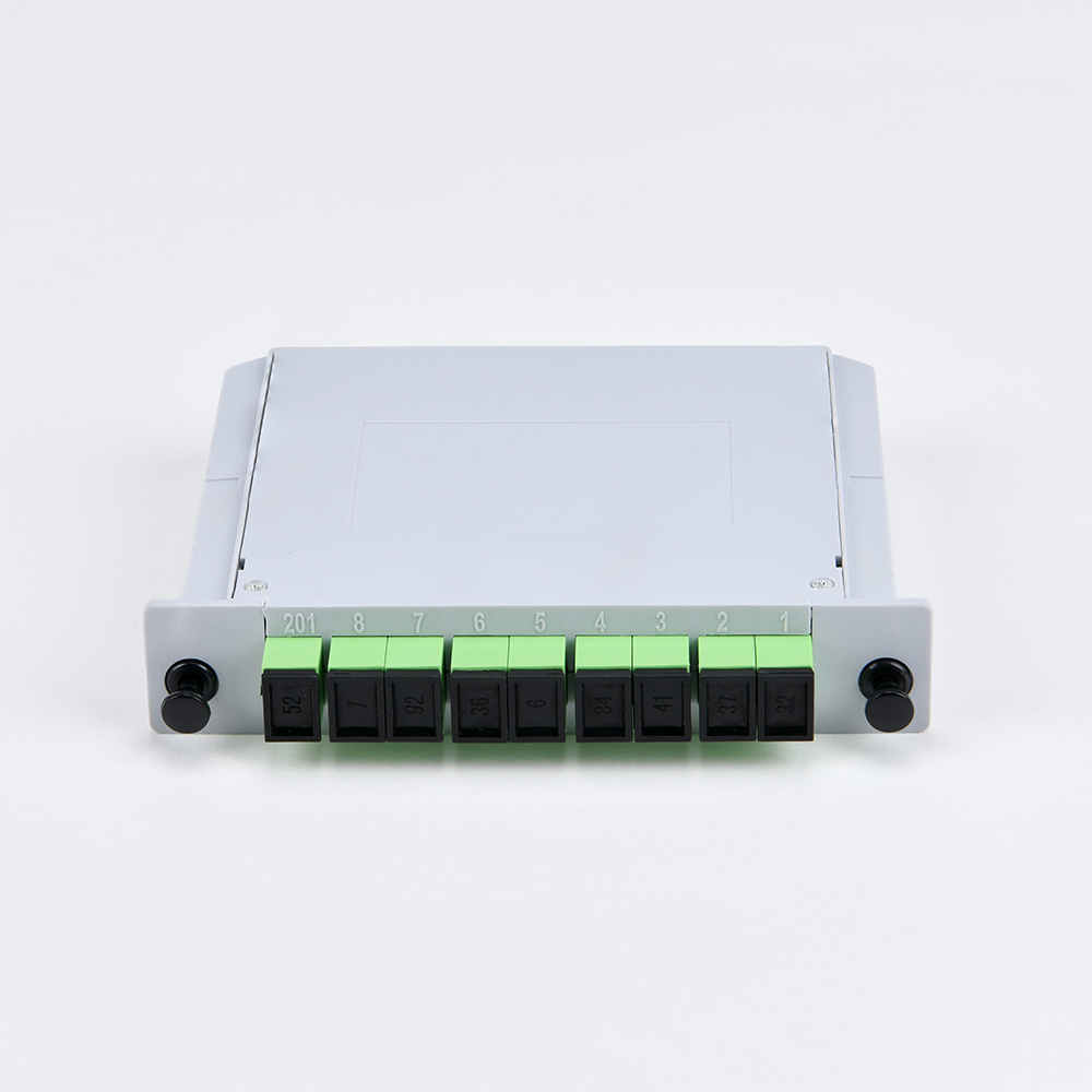
LGX Insert Cassette Type Splitter
Fiber optic PLC splitter, also known as a beam splitter, is an integrated waveguide optical power distribution device based on a quartz substrate. It is similar to a coaxial cable transmission system. The optical network system also requires an optical signal to be coupled to the branch distribution. The fiber optic splitter is one of the most important passive devices in the optical fiber link. It is an optical fiber tandem device with many input terminals and many output terminals. It is especially applicable to a passive optical network (EPON, GPON, BPON, FTTX, FTTH, etc.) to connect the ODF and the terminal equipment and to achieve the branching of the optical signal. -
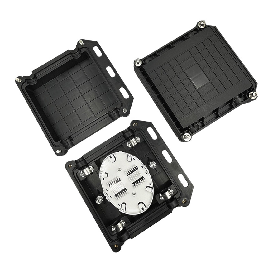
OYI-FOSC HO7
The OYI-FOSC-02H horizontal fiber optic splice closure has two connection options: direct connection and splitting connection. It is applicable in situations such as overhead, man-well of pipeline, and embedded situations, among others. Comparing with a terminal box, the closure requires much stricter sealing requirements. Optical splice closures are used to distribute, splice, and store outdoor optical cables that enter and exit from the ends of the closure. The closure has 2 entrance ports. The shell of the product is made from ABS+PP material. These closures provide excellent protection for fiber optic joints from outdoor environments such as UV, water, and weather, with leak-proof sealing and IP68 protection. -

OYI-FAT16F Series Terminal Box
The 16-core OYI-FAT16F optical terminal box performs in accordance with the industry standard requirements of YD/T2150-2010. It is mainly used in the FTTX (solutions) access system terminal link. The box is made of high-strength PC, ABS plastic alloy injection molding, which provides good sealing and aging resistance. In addition, it can be hung on the wall outdoors or indoors for installation and use. The OYI-FAT16F optical terminal box has an inner design with a single-layer structure, divided into the distribution line area, outdoor cable insertion, fiber splicing tray, and FTTH drop optical cable storage. The fiber optical lines are very clear, making it convenient to operate and maintain. There are 3 cable holes under the box that can accommodate 3 outdoor optical cables for direct or different junctions, and it can also accommodate 16 FTTH drop optical cables for end connections. The fiber splicing tray uses a flip form and can be configured with 16 cores capacity specifications to accommodate the box’s expansion needs. -
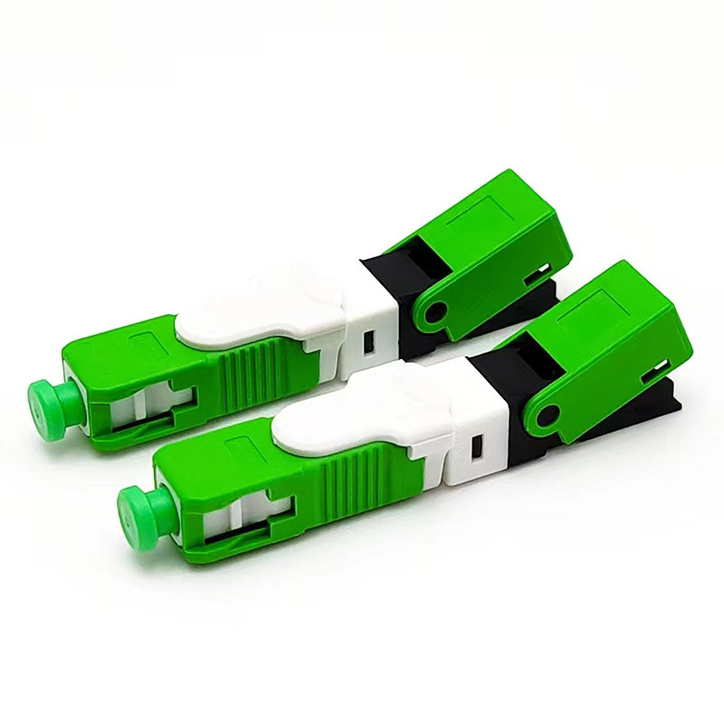
OYI A Type Fast Connector
Our fiber optic fast connector, the OYI A type, is designed for FTTH (Fiber To The Home), FTTX (Fiber To The X). It is a new generation of fiber connector used in assembly and can provide open flow and precast types, with optical and mechanical specifications that meet the standard for optical fiber connectors. It is designed for high quality and high efficiency during installation, and the structure of the crimping position is a unique design. -

Jacket Round Cable
Fiber optic drop cable also called double sheath fiber drop cable is an assembly designed to transfer information by light signal in last mile internet constructions.Optic drop cables usually consist of one or more fiber cores, reinforced and protected by special materials to have superior physical performance to applied in various applications -

Module OYI-1L311xF
OYI-1L311xF Small Form Factor Pluggable (SFP) transceivers are compatible with the Small Form Factor Pluggable Multi-Sourcing Agreement (MSA), The transceiver consists of five sections: the LD driver, the limiting amplifier, the digital diagnostic monitor, the FP laser and the PIN photo-detector, the module data link up to 10km in 9/125um single mode fiber. The optical output can be disabled by a TTL logic high-level input of Tx Disable, and the system also 02 can disable the module via I2C. Tx Fault is provided to indicate that degradation of the laser. Loss of signal (LOS) output is provided to indicate the loss of an input optical signal of receiver or the link status with partner. The system can also get the LOS (or Link)/Disable/Fault information via I2C register access.
If you're looking for a reliable, high-speed fibre optic cable solution, look no further than OYI. Contact us now to see how we can help you stay connected and take your business to the next level.
