 0755-23179541
  sales@oyii.net
.png) 8618926041961
8618926041961
Module OYI-1L311xF
1250Mb/s SFP 1310nm 10km Optical Transceiver
Module OYI-1L311xF
Product Description
OYI-1L311xF Small Form Factor Pluggable (SFP) transceivers are compatible with the Small Form Factor Pluggable Multi-Sourcing Agreement (MSA), The transceiver consists of five sections: the LD driver, the limiting amplifier, the digital diagnostic monitor, the FP laser and the PIN photo-detector, the module data link up to 10km in 9/125um single mode fiber.
The optical output can be disabled by a TTL logic high-level input of Tx Disable, and the system also 02 can disable the module via I2C. Tx Fault is provided to indicate that degradation of the laser. Loss of signal (LOS) output is provided to indicate the loss of an input optical signal of receiver or the link status with partner. The system can also get the LOS (or Link)/Disable/Fault information via I2C register access.
Product Features
1. Up to 1250Mb/s data links.
2. 1310nm FP laser transmitter and PIN photo-detector.
3. Up to 10km on 9/125µm SMF.
4. Hot-pluggable SFP footprint.
5. Duplex LC/UPC type pluggable optical interface.
6. Low power dissipation.
7. Metal enclosure, for lower EMI.
8. RoHS compliant and lead-free.
9. Support Digital Diagnostic Monitoring interface.
10. Single +3.3V power supply.
11. Compliant with SFF-8472.
12. Case operating temperature
Commercial: 0 ~ +70℃
Extended: -10 ~ +80℃
Industrial: -40 ~ +85℃
Applications
1. Switch to Switch Interface.
2. Gigabit Ethernet.
3. Switched Backplane Applications.
4. Router/Server Interface.
5. Other Optical Links.
Absolute Maximum Ratings
It has to be noted that the operation in excess of any individual absolute maximum ratings might cause permanent damage to this module.
|
Parameter |
Symbol |
Min |
Max |
Unit |
Notes |
|
Storage Temperature |
TS |
-40 |
85 |
°C |
|
|
Power Supply Voltage |
VCC |
-0.3 |
3.6 |
V |
|
|
Relative Humidity (non-condensation) |
RH |
5 |
95 |
% |
|
|
Damage Threshold |
THd |
5 |
|
dBm |
|
2.Recommended Operating Conditions and Power Supply Requirements
|
Parameter |
Symbol |
Min |
Typical |
Max |
Unit |
Notes |
|
Operating Case Temperature |
TOP |
0 |
|
70 |
°C |
commercial |
|
-10 |
|
80 |
extended |
|||
|
-40 |
|
85 |
industrial |
|||
|
Power Supply Voltage |
VCC |
3.135 |
3.3 |
3.465 |
V |
|
|
Data Rate |
|
|
1250 |
|
Mb/s |
|
|
Control Input Voltage High |
|
2 |
|
Vcc |
V |
|
|
Control Input Voltage Low |
|
0 |
|
0.8 |
V |
|
|
Link Distance (SMF) |
D |
|
|
10 |
km |
9/125um |
3.Pin Assignment and Pin Description
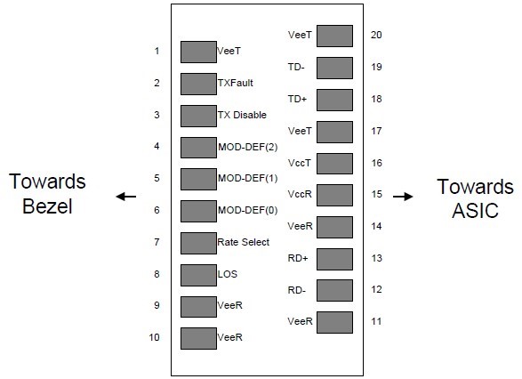
Figure1. Diagram of host board connector block pin numbers and names
|
PIN |
Name |
Name/Description |
Notes |
|
1 |
VEET |
Transmitter Ground (Common with Receiver Ground) |
1 |
|
2 |
TXFAULT |
Transmitter Fault. |
|
|
3 |
TXDIS |
Transmitter Disable. Laser output disabled on high or open. |
2 |
|
4 |
MOD_DEF(2) |
Module Definition 2. Data line for Serial ID. |
3 |
|
5 |
MOD_DEF(1) |
Module Definition 1. Clock line for Serial ID. |
3 |
|
6 |
MOD_DEF(0) |
Module Definition 0. Grounded within the module. |
3 |
|
7 |
Rate Select |
No connection required |
4 |
|
8 |
LOS |
Loss of Signal indication. Logic 0 indicates normal operation. |
5 |
|
9 |
VEER |
Receiver Ground (Common with Transmitter Ground) |
1 |
|
10 |
VEER |
Receiver Ground (Common with Transmitter Ground) |
1 |
|
11 |
VEER |
Receiver Ground (Common with Transmitter Ground) |
1 |
|
12 |
RD- |
Receiver Inverted DATA out. AC Coupled |
|
|
13 |
RD+ |
Receiver Non-inverted DATA out. AC Coupled |
|
|
14 |
VEER |
Receiver Ground (Common with Transmitter Ground) |
1 |
|
15 |
VCCR |
Receiver Power Supply |
|
|
16 |
VCCT |
Transmitter Power Supply |
|
|
17 |
VEET |
Transmitter Ground (Common with Receiver Ground) |
1 |
|
18 |
TD+ |
Transmitter Non-Inverted DATA in. AC Coupled. |
|
|
19 |
TD- |
Transmitter Inverted DATA in. AC Coupled. |
|
|
20 |
VEET |
Transmitter Ground (Common with Receiver Ground) |
1 |
Notes:
1. Circuit ground is internally isolated from chassis ground.
2. Laser output disabled on TDIS >2.0V or open, enabled on TDIS <0.8V.
3. Should be pulled up with 4.7k-10k ohms on host board to a voltage between 2.0V and 3.6V.MOD_DEF
(0) pulls line low to indicate module is plugged in.
4. This is an optional input used to control the receiver bandwidth for compatibility with multiple data rates (most likely Fiber Channel 1x and 2x Rates).If implemented, the input will be internally pulled down with > 30kΩ resistor. The input states are:
1) Low (0 – 0.8V): Reduced Bandwidth 2) (>0.8, < 2.0V): Undefined
3) High (2.0 – 3.465V): Full Bandwidth
4) Open: Reduced Bandwidth
5. LOS is open collector output should be pulled up with 4.7k-10k ohms on host board to a voltage between 2.0V and 3.6V. Logic 0 indicates normal operation; logic 1 indicates loss of signal.
Specification of Transmitter Electrical Characteristics
The following electrical characteristics are defined over the Recommended Operating Environment unless otherwise specified.
|
Parameter |
Symbol |
Min. |
|
Typical |
|
Max |
Unit |
Notes |
||
|
Power Consumption |
P |
|
|
|
|
0.85 |
W |
commercial |
||
|
|
|
|
|
0.9 |
Industrial |
|||||
|
Supply Current |
Icc |
|
|
|
|
250 |
mA |
commercial |
||
|
|
|
|
|
270 |
Industrial |
|||||
|
|
|
Transmitter |
|
|
|
|
||||
|
Single-ended Input Voltage Tolerance |
VCC |
-0.3 |
|
|
4.0 |
V |
|
|||
|
Differential Input Voltage Swing |
Vin,pp |
200 |
|
|
2400 |
mVpp |
|
|||
|
Differential Input Impedance |
Zin |
90 |
|
100 |
110 |
Ohm |
|
|||
|
Transmit Disable Assert Time |
|
|
|
|
5 |
us |
|
|||
|
Transmit Disable Voltage |
Vdis |
Vcc-1.3 |
|
|
Vcc |
V |
|
|||
|
Transmit Enable Voltage |
Ven |
Vee-0.3 |
|
|
0.8 |
V |
|
|||
|
Receiver |
||||||||||
|
Differential Output Voltage Swing |
Vout,pp |
500 |
|
|
900 |
mVpp |
|
|||
|
Differential Output Impedance |
Zout |
90 |
|
100 |
110 |
Ohm |
|
|||
|
Data output rise/fall time |
Tr/Tf |
|
|
100 |
|
ps |
20% to 80% |
|||
|
LOS Assert Voltage |
VlosH |
Vcc-1.3 |
|
|
Vcc |
V |
|
|||
|
LOS De-assert Voltage |
VlosL |
Vee-0.3 |
|
|
0.8 |
V |
|
|||
Optical Characteristics
The following optical characteristics are defined over the Recommended Operating Environment unless otherwise specified.
|
Parameter |
Symbol |
Min. |
Typical |
Max |
Unit |
Notes |
|
|
Transmitter |
|
||||
|
Center Wavelength |
λC |
1270 |
1310 |
1360 |
nm |
|
|
Spectrum Bandwidth(RMS) |
σ |
|
|
3.5 |
nm |
|
|
Average Optical Power |
PAVG |
-9 |
|
-3 |
dBm |
1 |
|
Optical Extinction Ratio |
ER |
9 |
|
|
dB |
|
|
Transmitter OFF Output Power |
POff |
|
|
-45 |
dBm |
|
|
Transmitter Eye Mask |
|
Compliant with 802.3z(class 1 laser safety) |
2 |
|||
|
|
Receiver |
|
||||
|
Center Wavelength |
λC |
1270 |
|
1610 |
nm |
|
|
Receiver Sensitivity (Average Power) |
Sen. |
|
|
-20 |
dBm |
3 |
|
Input Saturation Power (overload) |
Psat |
-3 |
|
|
dBm |
|
|
LOS Assert |
LOSA |
-36 |
|
|
dB |
4 |
|
LOS De-assert |
LOSD |
|
|
-21 |
dBm |
4 |
|
LOS Hysteresis |
LOSH |
0.5 |
|
|
dBm |
|
Notes:
1.Measure at 2^7-1 NRZ PRBS pattern
2.Transmitter eye mask definition.
3.Measured with Light source 1310nm, ER=9dB; BER =<10^-12
@PRBS=2^7-1 NRZ
4.When LOS de-asserted, the RX data+/- output is High-level(fixed).

Digital Diagnostic Functions
The following digital diagnostic characteristics are defined over the Recommended Operating Environment unless otherwise specified. It is compliant to SFF-8472 Rev10.2 with internal calibration mode. For external calibration mode please contact our sales staff.
|
Parameter |
Symbol |
Min. |
Max |
Unit |
Notes |
|
Temperature monitor absolute error |
DMI_ Temp |
-3 |
3 |
°C |
Over operating temp |
|
Supply voltage monitor absolute error |
DMI _VCC |
-0.15 |
0.15 |
V |
Full operating range |
|
RX power monitor absolute error |
DMI_RX |
-3 |
3 |
dB |
|
|
Bias current monitor |
DMI_ bias |
-10% |
10% |
mA |
|
|
TX power monitor absolute error |
DMI_TX |
-3 |
3 |
dB |
|
Mechanical Dimensions
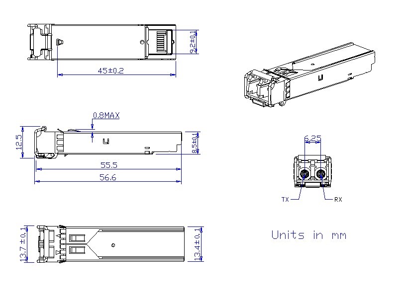
Figure2. Mechanical Outline
Ordering Information
|
Part Number |
Data Rate (Gb/s) |
Wavelength (nm) |
Transmission Distance(km) |
Temperature (oC) (Operating Case) |
|
OYI-1L311CF |
1.25 |
1310 |
10km SMF |
0~70 commercial |
|
OYI-1L311EF |
1.25 |
1310 |
10km SMF |
-10~80 Extended |
|
OYI-1L311IF |
1.25 |
1310 |
10km SMF |
-40~85 Industrial |
-
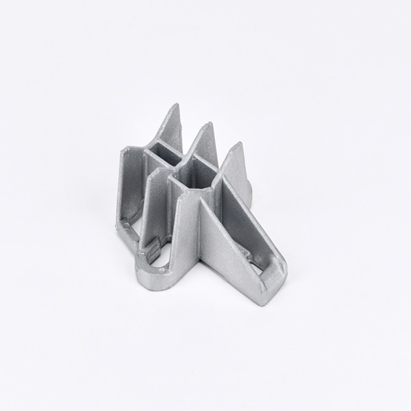
UPB Aluminum Alloy Universal Pole Bracket
The universal pole bracket is a functional product that plays a vital role in various industries. It is mainly made of aluminum alloy, which gives it high mechanical strength, making it both high-quality and durable. Its unique patented design allows for a common hardware fitting that can cover all installation situations, whether on wooden, metal, or concrete poles. It is used with stainless steel bands and buckles to fix the cable accessories during installation. -

OYI-IW series
Indoor Wall-mount Fiber Optic Distribution Frame can manage both single fiber and ribbon & bundle fiber cables for indoor using. It is an integrated unit for fiber management, and can be used as distribution box, this equipment function is to fix and manage the fiber optic cables inside the box as well as provide protection. Fiber optic termination box is modular so they are applying cable to your existing systems without any modification or additional work. Suitable for installation of FC, SC, ST, LC, etc. adaptors, and suitable for fiber optic pigtail or plastic box type PLC splitters. and large working space to integrate the pigtails, cables and adapters. -

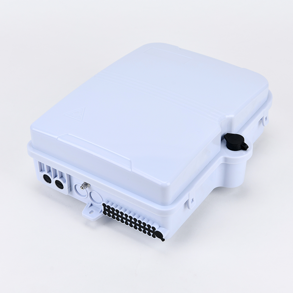
OYI-FTB-10A Terminal Box
The equipment is used as a termination point for the feeder cable to connect with drop cable in FTTx communication network system. The fiber splicing, splitting, distribution can be done in this box, and meanwhile it provides solid protection and management for the FTTx network building. -
OYI-FAT24A Terminal Box
The 24-core OYI-FAT24A optical terminal box performs in accordance with the industry standard requirements of YD/T2150-2010. It is mainly used in the FTTX access system terminal link. The box is made of high-strength PC, ABS plastic alloy injection molding, which provides good sealing and aging resistance. In addition, it can be hung on the wall outdoors or indoors for installation and use. -
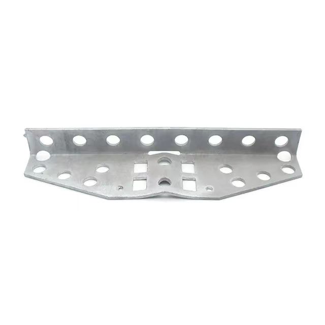
Galvanized Brackets CT8, Drop Wire Cross-arm Br...
It is made from carbon steel with hot-dipped zinc surface processing, which can last a very long time without rusting for outdoor purposes. It is widely used with SS bands and SS buckles on poles to hold accessories for telecom installations. The CT8 bracket is a type of pole hardware used to fix distribution or drop lines on wooden, metal, or concrete poles. The material is carbon steel with a hot-dip zinc surface. The normal thickness is 4mm, but we can provide other thicknesses upon request. The CT8 bracket is an excellent choice for overhead telecommunication lines as it allows for multiple drop wire clamps and dead-ending in all directions. When you need to connect many drop accessories on one pole, this bracket can meet your requirements. The special design with multiple holes allows you to install all accessories in one bracket. We can attach this bracket to the pole using two stainless steel bands and buckles or bolts. -

OYI J Type Fast Connector
Our fiber optic fast connector, the OYI J type, is designed for FTTH (Fiber to The Home), FTTX (Fiber To The X). It is a new generation of fiber connector used in assembly that provides open flow and precast types, meeting the optical and mechanical specifications of standard optical fiber connectors. It is designed for high quality and high efficiency during installation.Mechanical connectors make fiber terminations quick, easy, and reliable. These fiber optic connectors offer terminations without any hassle and require no epoxy, no polishing, no splicing, and no heating, achieving similar excellent transmission parameters as standard polishing and splicing technology. Our connector can greatly reduce the assembly and setup time. The pre-polished connectors are mainly applied to FTTH cables in FTTH projects, directly at the end-user site.
If you're looking for a reliable, high-speed fibre optic cable solution, look no further than OYI. Contact us now to see how we can help you stay connected and take your business to the next level.
