 0755-23179541
  sales@oyii.net
.png) 8618926041961
8618926041961
SFP-ETRx-4
10/100/1000 BASE-T Copper SFP Transceiver
SFP-ETRx-4
Product Description
The ER4 is a transceiver module designed for 40km optical communication applications. The design is compliant to 40GBASE-ER4 of the IEEE P802.3ba standard. The module converts 4 inputs channels (ch) of 10Gb/s electrical data to 4 CWDM optical signals, and multiplexes them into a single channel for 40Gb/s optical transmission. Reversely, on the receiver side, the module optically demultiplexes a 40Gb/s input into 4 CWDM channels signals, and converts them to 4 channel output electrical data.
The central wavelengths of the 4 CWDM channels are 1271, 1291, 1311 and 1331 nm as members of the CWDM wavelength grid defined in ITU-T G694.2. It contains a duplex LC Adapter for the optical interface and a 38-pin adapter for the electrical interface. To minimize the optical dispersion in the long-haul system, single-mode fiber (SMF) has to be applied in this module.
The product is designed with form factor, optical/electrical connection and digital diagnostic interface according to the QSFP Multi-Source Agreement (MSA). It has been designed to meet the harshest external operating conditions including temperature, humidity and EMI interference.
The module operates from a single +3.3V power supply and LVCMOS/LVTTL global control signals such as Module Present, Reset, Interrupt and Low Power Mode are available with the modules. A 2-wire serial interface is available to send and receive more complex control signals and to obtain digital diagnostic information. Individual channels can be addressed and unused channels can be shut down for maximum design flexibility.
The TQP10 is designed with form factor, optical/electrical connection and digital diagnostic interface according to the QSFP Multi-Source Agreement (MSA). It has been designed to meet the harshest external operating conditions including temperature, humidity and EMI interference. The module offers very high functionality and feature integration, accessible via a two-wire serial interface.
Product Features
1. 4 CWDM lanes MUX/DEMUX design.
2. Up to 11.2Gbps per channel bandwidth.
3. Aggregate bandwidth of > 40Gbps.
4. Duplex LC connector.
5. Compliant with 40G Ethernet IEEE802.3ba and 40GBASE-ER4 Standard.
6. QSFP MSA compliant.
7. APD photo-detector.
8. Up to 40 km transmission.
9. Compliant with QDR/DDR Infini band data rates.
10. Single +3.3V power supply operating.
11. Built-in digital diagnostic functions.
12. Temperature range 0°C to 70°C.
13. RoHS Compliant Part.
Applications
1. Rack to rack.
2. Data centers Switches and Routers.
3. Metro networks.
4. Switches and Routers.
5. 40G BASE-ER4 Ethernet Links.
|
Transmitter |
|
|
|
|
|
||
|
Single Ended Output Voltage Tolerance |
|
0.3 |
|
4 |
V |
1 |
|
|
Common mode Voltage Tolerance |
|
15 |
|
|
mV |
|
|
|
Transmit Input Diff Voltage |
VI |
150 |
|
1200 |
mV |
|
|
|
Transmit Input Diff Impedance |
ZIN |
85 |
100 |
115 |
|
|
|
|
Data Dependent Input Jitter |
DDJ |
|
0.3 |
|
UI |
|
|
|
|
Receiver |
|
|
|
|
|
|
|
Single Ended Output Voltage Tolerance |
|
0.3 |
|
4 |
V |
|
|
|
Rx Output Diff Voltage |
Vo |
370 |
600 |
950 |
mV |
|
|
|
Rx Output Rise and Fall Voltage |
Tr/Tf |
|
|
35 |
ps |
1 |
|
|
Total Jitter |
TJ |
|
0.3 |
|
UI |
|
|
Note:
1.20~80%
Optical Parameters (TOP = 0 to 70 °C, VCC = 3.0 to 3.6 Volts)
|
Parameter |
Symbol |
Min |
Typ |
Max |
Unit |
Ref. |
|
|
Transmitter |
|
|
|||
|
Wavelength Assignment |
L0 |
1264.5 |
1271 |
1277.5 |
nm |
|
|
L1 |
1284.5 |
1291 |
1297.5 |
nm |
|
|
|
L2 |
1304.5 |
1311 |
1317.5 |
nm |
|
|
|
L3 |
1324.5 |
1331 |
1337.5 |
nm |
|
|
|
Side-mode Suppression Ratio |
SMSR |
30 |
- |
- |
dB |
|
|
Total Average Launch Power |
PT |
- |
- |
10.5 |
dBm |
|
|
Transmit OMA per Lane |
TxOMA |
0 |
|
5.0 |
dBm |
|
|
Average Launch Power, each Lane |
TXPx |
0 |
|
5.0 |
dBm |
|
|
Difference in Launch Power between any two Lanes (OMA) |
|
- |
- |
4.7 |
dB |
|
|
TDP, each Lane |
TDP |
|
|
2.6 |
dB |
|
|
Extinction Ratio |
ER |
5.5 |
6.5 |
|
dB |
|
|
Transmitter Eye Mask Definition {X1, X2, X3, Y1, Y2, Y3} |
|
{0.25,0.4,0.45,0.25,0.28,0.4} |
|
|
||
|
Optical Return Loss Tolerance |
|
- |
- |
20 |
dB |
|
|
Average Launch Power OFF Transmitter, each Lane |
Poff |
|
|
-30 |
dBm |
|
|
Relative Intensity Noise |
Rin |
|
|
-128 |
dB/HZ |
1 |
|
Optical Return Loss Tolerance |
|
- |
- |
12 |
dB |
|
|
|
Receiver |
|
|
|||
|
Damage Threshold |
THd |
0 |
|
|
dBm |
1 |
|
Receiver Sensitivity (OMA) per Lane |
Rxsens |
-21 |
|
-6 |
dBm |
|
|
Receiver Power (OMA), each Lane |
RxOMA |
- |
- |
-4 |
dBm |
|
|
Stressed Receiver Sensitivity (OMA) per Lane |
SRS |
|
|
-16.8 |
dBm |
|
|
RSSI Accuracy |
|
-2 |
|
2 |
dB |
|
|
Receiver Reflectance |
Rrx |
|
|
-26 |
dB |
|
|
Receive Electrical 3 dB upper Cutoff Frequency, each Lane |
|
|
|
12.3 |
GHz |
|
|
LOS De-Assert |
LOSD |
|
|
-23 |
dBm |
|
|
LOS Assert |
LOSA |
-33 |
|
|
dBm |
|
|
LOS Hysteresis |
LOSH |
0.5 |
|
|
dB |
|
Note
1. 12dB Reflection
Diagnostic Monitoring Interface
Digital diagnostics monitoring function is available on all QSFP+ ER4. A 2-wire serial interface provides user to contact with module. The structure of the memory is shown in flowing. The memory space is arranged into a lower, single page, address space of 128 bytes and multiple upper address space pages. This structure permits timely access to addresses in the lower page, such as Interrupt
Flags and Monitors. Less time critical time entries, such as serial ID information and threshold settings, are available with the Page Select function. The interface address used is A0xh and is mainly used for time critical data like interrupt handling in order to enable a one-time-read for all data related to an interrupt situation. After an interrupt, Intl has been asserted, the host can read out the flag field to determine the affected channel and type of flag.
EEPROM Serial ID Memory Contents (A0h)
|
Data Address |
Length (Byte) |
Name of Length |
Description and Contents |
|
Base ID Fields |
|||
|
128 |
1 |
Identifier |
Identifier Type of serial Module(D=QSFP+) |
|
129 |
1 |
Ext. Identifier |
Extended Identifier of Serial Module(90=2.5W) |
|
130 |
1 |
Connector |
Code of connector type(7=LC) |
|
131-138 |
8 |
Specification compliance |
Code for electronic compatibility or optical compatibility(40GBASE-LR4) |
|
139 |
1 |
Encoding |
Code for serial encoding algorithm(5=64B66B) |
|
140 |
1 |
BR, Nominal |
Nominal bit rate, units of 100 MB its/s(6C=108) |
|
141 |
1 |
Extended rates elect Compliance |
Tags for extended rate select compliance |
|
142 |
1 |
Length (SMF) |
Link length supported for SMF fiber in km (28=40KM) |
|
143 |
1 |
Length (OM3 50um) |
Link length supported for EBW 50/125um fiber (OM3), units of 2m |
|
144 |
1 |
Length (OM2 50um) |
Link length supported for 50/125um fiber (OM2), units of 1m |
|
145 |
1 |
Length (OM1 62.5um) |
Link length supported for 62.5/125um fiber (OM1), units of 1m |
|
146 |
1 |
Length (Copper) |
Link length of copper or active cable, unites of 1m Link length supported for 50/125um fiber (OM4), units of 2m when Byte 147 declares 850nm VCSEL as defined in Table 37 |
|
147 |
1 |
Device tech |
Device technology |
|
148-163 |
16 |
Vendor name |
QSFP+ vendor name: TIBTRONIX (ASCII) |
|
164 |
1 |
Extended Module |
Extended Module codes for InfiniBand |
|
165-167 |
3 |
Vendor OUI |
QSFP+ vendor IEEE company ID (000840) |
|
168-183 |
16 |
Vendor PN |
Part number: TQPLFG40D (ASCII) |
|
184-185 |
2 |
Vendor rev |
Revision level for part number provided by vendor (ASCII) (X1) |
|
186-187 |
2 |
Wave length or Copper cable Attenuation |
Nominal laser wavelength (wavelength=value/20 in nm) or copper cable attenuation in dB at 2.5GHz (Adrs 186) and 5.0GHz (Adrs 187) (65A4=1301) |
|
188-189 |
2 |
Wavelength tolerance |
Guaranteed range of laser wavelength (+/- value) from nominal wavelength. (wavelength Tol=value/200 in nm) (1C84=36.5) |
|
190 |
1 |
Max case temp |
Maximum case temperature in degrees C (70) |
|
191 |
1 |
CC_BASE |
Check code for base ID fields (addresses 128-190) |
Transceiver Block Diagram

Mechanical Dimensions

-

Fanout Multi-core (4~144F) 0.9mm Connectors Pat...
OYI fiber optic fanout multi-core patch cord, also known as a fiber optic jumper, is composed of a fiber optic cable terminated with different connectors at each end. Fiber optic patch cables are used in two major application areas: connecting computer workstations to outlets and patch panels or optical cross-connect distribution centers. OYI provides various types of fiber optic patch cables, including single-mode, multi-mode, multi-core, armored patch cables, as well as fiber optic pigtails and other special patch cables. For most patch cables, connectors such as SC, ST, FC, LC, MU, MTRJ, and E2000 (with APC/UPC polish) are all available. -

OYI3434G4R
ONU product is the terminal equipment of a series of XPON which comply fully with ITU-G.984.1/2/3/4 standard and meet the energy-saving of G.987.3 protocol,ONU is based on mature and stable and high cost-effective GPON technology which adopts high-performance XPON REALTEK chipset and has high reliability , easy management, flexible configuration, robustness, good quality service guarantee(Qos). -
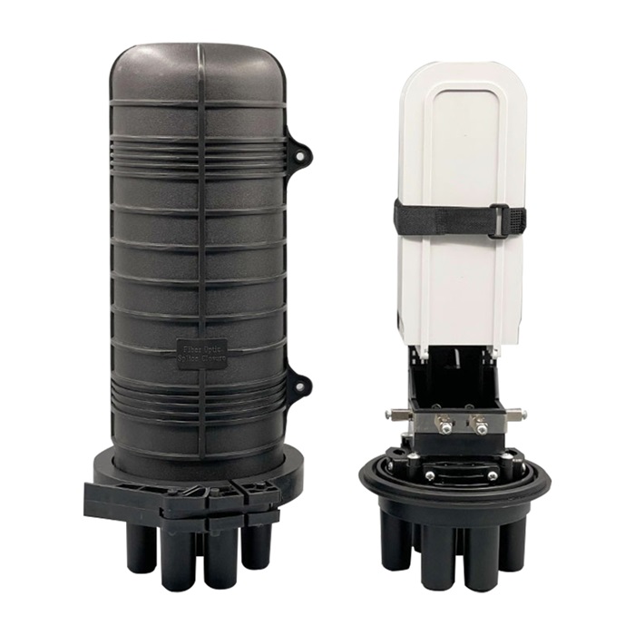
OYI-FOSC-D103H
The OYI-FOSC-D103H dome fiber optic splice closure is used in aerial, wall-mounting, and underground applications for the straight-through and branching splice of the fiber cable. Dome splicing closures are excellent protection of fiber optic joints from outdoor environments such as UV, water, and weather, with leak-proof sealing and IP68 protection. The closure has 5 entrance ports on the end (4 round ports and 1 oval port). The shell of the product is made from ABS/PC+ABS material. The shell and the base are sealed by pressing the silicone rubber with the allocated clamp. The entry ports are sealed by heat-shrinkable tubes. The closures can be opened again after being sealed and reused without changing the sealing material. The closure’s main construction includes the box, splicing, and it can be configured with adapters and optical splitters. -
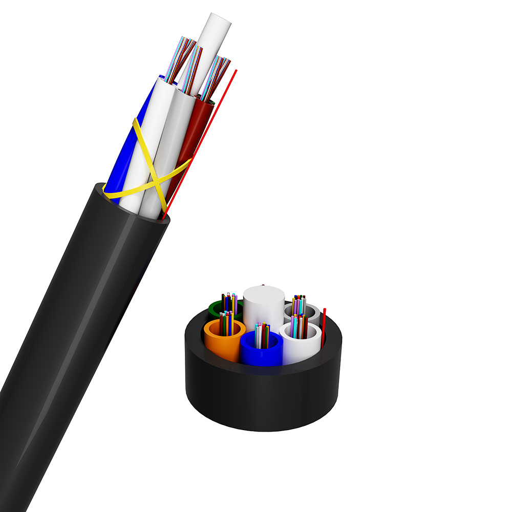
Air Blowing Mini Optical Fibre Cable
The optical fiber is placed inside a loose tube made of high-modulus hydrolyzable material. The tube is then filled with thixotropic, water-repellent fiber paste to form a loose tube of optical fiber. A plurality of fiber optic loose tubes, arranged according to color order requirements and possibly including filler parts, are formed around the central non-metallic reinforcement core to create the cable core via SZ stranding. The gap in the cable core is filled with dry, water-retaining material to block water. A layer of polyethylene (PE) sheath is then extruded. The optical cable is laid by air blowing microtube. First, the air blowing microtube is laid in the outer protection tube, and then the micro cable is laid in the intake air blowing microtube by air blowing. This laying method has a high fiber density, which greatly improves the utilization rate of the pipeline. It is also easy to expand the pipeline capacity and diverge the optical cable. -
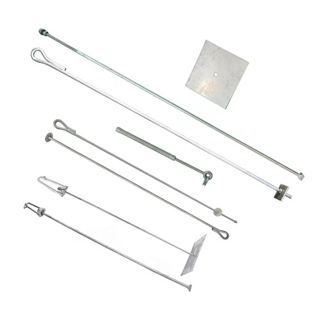
Stay Rod
This stay rod is used to connect the stay wire to the ground anchor, also known as the stay set. It ensures that the wire is firmly rooted to the ground and everything remains stable. There are two types of stay rods available in the market: the bow stay rod and the tubular stay rod. The difference between these two types of power-line accessories is based on their designs. -

Direct Installation (DI) 24-way 8/5mm+1-way 10/...
A bundle of micro- or mini-tubes with strengthened wall thickness is encased in a single thin HDPE sheath, forming a duct assembly specifically engineered for fiber optical cable deployment. This robust design enables versatile installation—either retrofitted into existing ducts or directly buried underground—supporting seamless integration into fiber optical cable networks. The micro ducts are optimized for high-efficiency fiber optical cable blowing, featuring an ultra-smooth inner surface with low-friction properties to minimize resistance during air-assisted cable insertion. Each micro duct is color-coded per Figure 1, facilitating quick identification and routing of fiber optical cable types (e.g., single-mode, multi-mode) during network installation and maintenance.
If you're looking for a reliable, high-speed fibre optic cable solution, look no further than OYI. Contact us now to see how we can help you stay connected and take your business to the next level.
