 0755-23179541
  sales@oyii.net
SFP-ETRx-4
10/100/1000 BASE-T Copper SFP Transceiver
SFP-ETRx-4
Product Description
The ER4 is a transceiver module designed for 40km optical communication applications. The design is compliant to 40GBASE-ER4 of the IEEE P802.3ba standard. The module converts 4 inputs channels (ch) of 10Gb/s electrical data to 4 CWDM optical signals, and multiplexes them into a single channel for 40Gb/s optical transmission. Reversely, on the receiver side, the module optically demultiplexes a 40Gb/s input into 4 CWDM channels signals, and converts them to 4 channel output electrical data.
The central wavelengths of the 4 CWDM channels are 1271, 1291, 1311 and 1331 nm as members of the CWDM wavelength grid defined in ITU-T G694.2. It contains a duplex LC Adapter for the optical interface and a 38-pin adapter for the electrical interface. To minimize the optical dispersion in the long-haul system, single-mode fiber (SMF) has to be applied in this module.
The product is designed with form factor, optical/electrical connection and digital diagnostic interface according to the QSFP Multi-Source Agreement (MSA). It has been designed to meet the harshest external operating conditions including temperature, humidity and EMI interference.
The module operates from a single +3.3V power supply and LVCMOS/LVTTL global control signals such as Module Present, Reset, Interrupt and Low Power Mode are available with the modules. A 2-wire serial interface is available to send and receive more complex control signals and to obtain digital diagnostic information. Individual channels can be addressed and unused channels can be shut down for maximum design flexibility.
The TQP10 is designed with form factor, optical/electrical connection and digital diagnostic interface according to the QSFP Multi-Source Agreement (MSA). It has been designed to meet the harshest external operating conditions including temperature, humidity and EMI interference. The module offers very high functionality and feature integration, accessible via a two-wire serial interface.
Product Features
1. 4 CWDM lanes MUX/DEMUX design.
2. Up to 11.2Gbps per channel bandwidth.
3. Aggregate bandwidth of > 40Gbps.
4. Duplex LC connector.
5. Compliant with 40G Ethernet IEEE802.3ba and 40GBASE-ER4 Standard.
6. QSFP MSA compliant.
7. APD photo-detector.
8. Up to 40 km transmission.
9. Compliant with QDR/DDR Infini band data rates.
10. Single +3.3V power supply operating.
11. Built-in digital diagnostic functions.
12. Temperature range 0°C to 70°C.
13. RoHS Compliant Part.
Applications
1. Rack to rack.
2. Data centers Switches and Routers.
3. Metro networks.
4. Switches and Routers.
5. 40G BASE-ER4 Ethernet Links.
|
Transmitter |
|
|
|
|
|
||
|
Single Ended Output Voltage Tolerance |
|
0.3 |
|
4 |
V |
1 |
|
|
Common mode Voltage Tolerance |
|
15 |
|
|
mV |
|
|
|
Transmit Input Diff Voltage |
VI |
150 |
|
1200 |
mV |
|
|
|
Transmit Input Diff Impedance |
ZIN |
85 |
100 |
115 |
|
|
|
|
Data Dependent Input Jitter |
DDJ |
|
0.3 |
|
UI |
|
|
|
|
Receiver |
|
|
|
|
|
|
|
Single Ended Output Voltage Tolerance |
|
0.3 |
|
4 |
V |
|
|
|
Rx Output Diff Voltage |
Vo |
370 |
600 |
950 |
mV |
|
|
|
Rx Output Rise and Fall Voltage |
Tr/Tf |
|
|
35 |
ps |
1 |
|
|
Total Jitter |
TJ |
|
0.3 |
|
UI |
|
|
Note:
1.20~80%
Optical Parameters (TOP = 0 to 70 °C, VCC = 3.0 to 3.6 Volts)
|
Parameter |
Symbol |
Min |
Typ |
Max |
Unit |
Ref. |
|
|
Transmitter |
|
|
|||
|
Wavelength Assignment |
L0 |
1264.5 |
1271 |
1277.5 |
nm |
|
|
L1 |
1284.5 |
1291 |
1297.5 |
nm |
|
|
|
L2 |
1304.5 |
1311 |
1317.5 |
nm |
|
|
|
L3 |
1324.5 |
1331 |
1337.5 |
nm |
|
|
|
Side-mode Suppression Ratio |
SMSR |
30 |
- |
- |
dB |
|
|
Total Average Launch Power |
PT |
- |
- |
10.5 |
dBm |
|
|
Transmit OMA per Lane |
TxOMA |
0 |
|
5.0 |
dBm |
|
|
Average Launch Power, each Lane |
TXPx |
0 |
|
5.0 |
dBm |
|
|
Difference in Launch Power between any two Lanes (OMA) |
|
- |
- |
4.7 |
dB |
|
|
TDP, each Lane |
TDP |
|
|
2.6 |
dB |
|
|
Extinction Ratio |
ER |
5.5 |
6.5 |
|
dB |
|
|
Transmitter Eye Mask Definition {X1, X2, X3, Y1, Y2, Y3} |
|
{0.25,0.4,0.45,0.25,0.28,0.4} |
|
|
||
|
Optical Return Loss Tolerance |
|
- |
- |
20 |
dB |
|
|
Average Launch Power OFF Transmitter, each Lane |
Poff |
|
|
-30 |
dBm |
|
|
Relative Intensity Noise |
Rin |
|
|
-128 |
dB/HZ |
1 |
|
Optical Return Loss Tolerance |
|
- |
- |
12 |
dB |
|
|
|
Receiver |
|
|
|||
|
Damage Threshold |
THd |
0 |
|
|
dBm |
1 |
|
Receiver Sensitivity (OMA) per Lane |
Rxsens |
-21 |
|
-6 |
dBm |
|
|
Receiver Power (OMA), each Lane |
RxOMA |
- |
- |
-4 |
dBm |
|
|
Stressed Receiver Sensitivity (OMA) per Lane |
SRS |
|
|
-16.8 |
dBm |
|
|
RSSI Accuracy |
|
-2 |
|
2 |
dB |
|
|
Receiver Reflectance |
Rrx |
|
|
-26 |
dB |
|
|
Receive Electrical 3 dB upper Cutoff Frequency, each Lane |
|
|
|
12.3 |
GHz |
|
|
LOS De-Assert |
LOSD |
|
|
-23 |
dBm |
|
|
LOS Assert |
LOSA |
-33 |
|
|
dBm |
|
|
LOS Hysteresis |
LOSH |
0.5 |
|
|
dB |
|
Note
1. 12dB Reflection
Diagnostic Monitoring Interface
Digital diagnostics monitoring function is available on all QSFP+ ER4. A 2-wire serial interface provides user to contact with module. The structure of the memory is shown in flowing. The memory space is arranged into a lower, single page, address space of 128 bytes and multiple upper address space pages. This structure permits timely access to addresses in the lower page, such as Interrupt
Flags and Monitors. Less time critical time entries, such as serial ID information and threshold settings, are available with the Page Select function. The interface address used is A0xh and is mainly used for time critical data like interrupt handling in order to enable a one-time-read for all data related to an interrupt situation. After an interrupt, Intl has been asserted, the host can read out the flag field to determine the affected channel and type of flag.
EEPROM Serial ID Memory Contents (A0h)
|
Data Address |
Length (Byte) |
Name of Length |
Description and Contents |
|
Base ID Fields |
|||
|
128 |
1 |
Identifier |
Identifier Type of serial Module(D=QSFP+) |
|
129 |
1 |
Ext. Identifier |
Extended Identifier of Serial Module(90=2.5W) |
|
130 |
1 |
Connector |
Code of connector type(7=LC) |
|
131-138 |
8 |
Specification compliance |
Code for electronic compatibility or optical compatibility(40GBASE-LR4) |
|
139 |
1 |
Encoding |
Code for serial encoding algorithm(5=64B66B) |
|
140 |
1 |
BR, Nominal |
Nominal bit rate, units of 100 MB its/s(6C=108) |
|
141 |
1 |
Extended rates elect Compliance |
Tags for extended rate select compliance |
|
142 |
1 |
Length (SMF) |
Link length supported for SMF fiber in km (28=40KM) |
|
143 |
1 |
Length (OM3 50um) |
Link length supported for EBW 50/125um fiber (OM3), units of 2m |
|
144 |
1 |
Length (OM2 50um) |
Link length supported for 50/125um fiber (OM2), units of 1m |
|
145 |
1 |
Length (OM1 62.5um) |
Link length supported for 62.5/125um fiber (OM1), units of 1m |
|
146 |
1 |
Length (Copper) |
Link length of copper or active cable, unites of 1m Link length supported for 50/125um fiber (OM4), units of 2m when Byte 147 declares 850nm VCSEL as defined in Table 37 |
|
147 |
1 |
Device tech |
Device technology |
|
148-163 |
16 |
Vendor name |
QSFP+ vendor name: TIBTRONIX (ASCII) |
|
164 |
1 |
Extended Module |
Extended Module codes for InfiniBand |
|
165-167 |
3 |
Vendor OUI |
QSFP+ vendor IEEE company ID (000840) |
|
168-183 |
16 |
Vendor PN |
Part number: TQPLFG40D (ASCII) |
|
184-185 |
2 |
Vendor rev |
Revision level for part number provided by vendor (ASCII) (X1) |
|
186-187 |
2 |
Wave length or Copper cable Attenuation |
Nominal laser wavelength (wavelength=value/20 in nm) or copper cable attenuation in dB at 2.5GHz (Adrs 186) and 5.0GHz (Adrs 187) (65A4=1301) |
|
188-189 |
2 |
Wavelength tolerance |
Guaranteed range of laser wavelength (+/- value) from nominal wavelength. (wavelength Tol=value/200 in nm) (1C84=36.5) |
|
190 |
1 |
Max case temp |
Maximum case temperature in degrees C (70) |
|
191 |
1 |
CC_BASE |
Check code for base ID fields (addresses 128-190) |
Transceiver Block Diagram

Mechanical Dimensions

-

GJYFKH
-
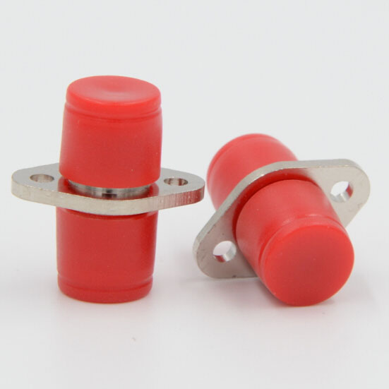
FC Type
Fiber optic adapter, sometimes also called a coupler, is a small device designed to terminate or link fiber optic cables or fiber optic connectors between two fiber optic lines. It contains the interconnect sleeve that holds two ferrules together. By precisely linking two connectors, fiber optic adapters allow the light sources to be transmitted at their maximum and minimize the loss as much as possible. At the same time, fiber optic adapters have the advantages of low insertion loss, good interchangeability, and reproducibility. They are used to connect optical fiber connectors such as FC, SC, LC, ST, MU, MTRJ, D4, DIN, MPO, etc. They are widely used in optical fiber communications equipment, measuring appliances, and so on. The performance is stable and reliable.
-
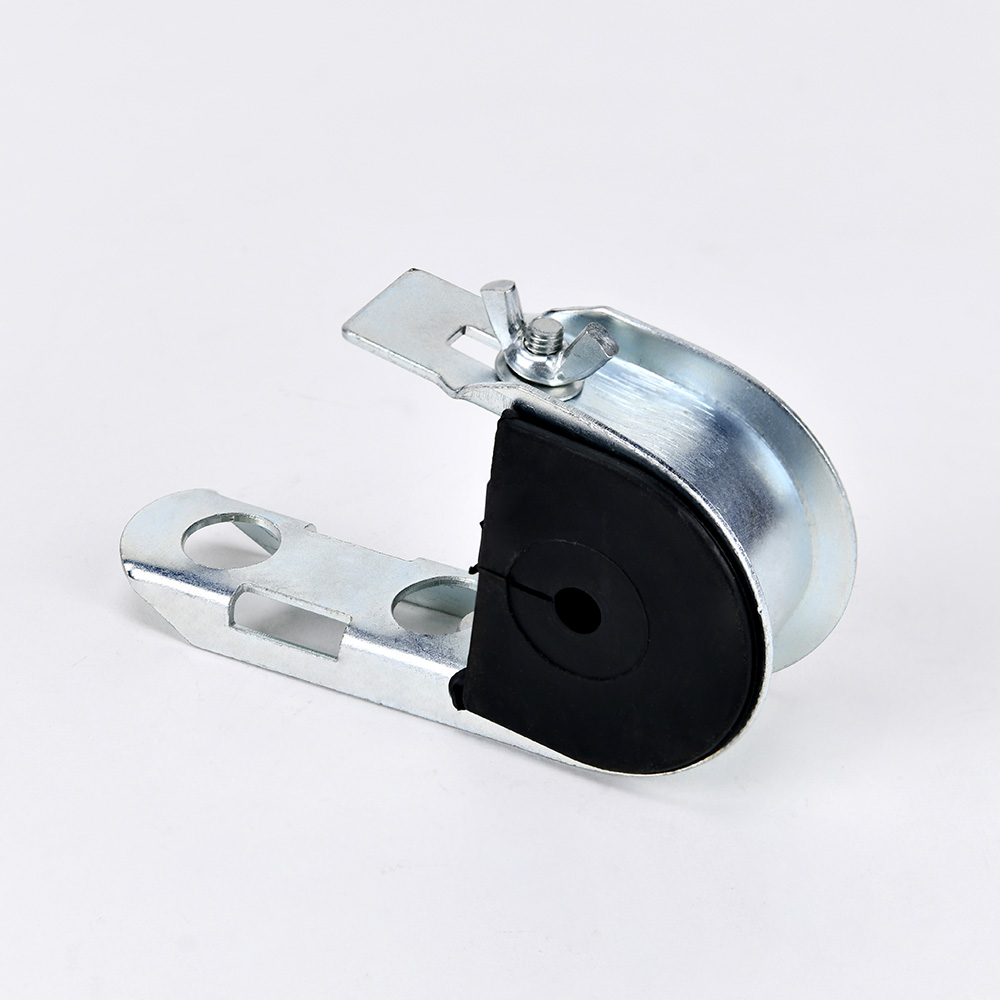
J Clamp J-Hook Small Type Suspension Clamp
OYI anchoring suspension clamp J hook is durable and of good quality, making it a worthwhile choice. It plays an important role in many industrial settings. The main material of the OYI anchoring suspension clamp is carbon steel, and the surface is electro galvanized, allowing it to last for a long period without rusting as a pole accessory. The J hook suspension clamp can be used with the OYI series stainless steel bands and buckles to fix cables onto poles, playing different roles in different places. Different cable sizes are available.
The OYI anchoring suspension clamp can be used to link signs and cable installations on posts. It is electro galvanized and can be used outside for more than 10 years without rusting. There are no sharp edges, and the corners are rounded. All items are clean, rust free, smooth, and uniform throughout, and free from burrs. It plays a huge role in industrial production.
-
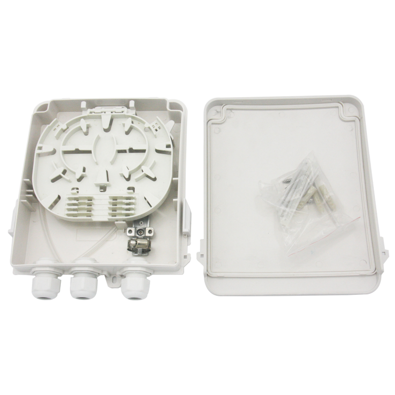
OYI-ATB08B Terminal Box
OYI-ATB08B 8-Cores Terminal box is developed and produced by the company itself. The product’s performance meets the requirements of industry standards YD/T2150-2010. It is suitable for installing multiple types of modules and can be applied to the work area wiring subsystem to achieve dual-core fiber access and port output. It provides fiber fixing, stripping, splicing, and protection devices, and allows for a small amount of redundant fiber inventory, making it suitable for FTTH (FTTH drop optical cables for end connections) system applications. The box is made of high-quality ABS plastic through injection molding, making it anti-collision, flame retardant, and highly impact-resistant. It has good sealing and anti-aging properties, protecting the cable exit and serving as a screen. It can be installed on the wall.
-
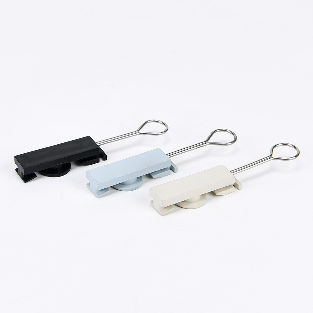
Drop Cable Anchoring Clamp S-Type
Drop wire tension clamp s-type, also called FTTH drop s-clamp, is developed to tension and support flat or round fiber optic cable on intermediate routes or last mile connections during outdoor overhead FTTH deployment. It is made of UV proof plastic and a stainless steel wire loop processed by injection molding technology.
-

OYI J Type Fast Connector
Our fiber optic fast connector, the OYI J type, is designed for FTTH (Fiber to The Home), FTTX (Fiber To The X). It is a new generation of fiber connector used in assembly that provides open flow and precast types, meeting the optical and mechanical specifications of standard optical fiber connectors. It is designed for high quality and high efficiency during installation.
Mechanical connectors make fiber terminations quick, easy, and reliable. These fiber optic connectors offer terminations without any hassle and require no epoxy, no polishing, no splicing, and no heating, achieving similar excellent transmission parameters as standard polishing and splicing technology. Our connector can greatly reduce the assembly and setup time. The pre-polished connectors are mainly applied to FTTH cables in FTTH projects, directly at the end-user site.
If you're looking for a reliable, high-speed fibre optic cable solution, look no further than OYI. Contact us now to see how we can help you stay connected and take your business to the next level.
