 0755-23179541
  sales@oyii.net
.png) 8618926041961
8618926041961

Direct Installation (DI) 24-way 8/5mm+1-way 10/8mm (PE Sheath 1.7mm)
HDPE Tube Bundle
Direct Installation (DI) 24-way 8/5mm+1-way 10/8mm (PE Sheath 1.7mm)
Product Features

The dimension of tube bundle shall be:
|
1) |
Inner Micro Duct: |
10/8mm(central duct) 8/5mm |
|
2) |
Outer Diameter: |
48.4mm (±s1.1mm) |
|
3) |
Thickness of sheathing: |
1.7mm |
(Figure 1)
Remarks: Ripcord is optional.
Raw materials:
HDPE of a high-molecular type with the following parameters is used for production of the Tube Bundle:
Melt flow index: 0.1 ~ 0.4 g/10 minutes NISO 1133 (190 °C, 2.16 KG)
Density: Min. 0.940 g/cm3 ISO 1183
Tensile strength at yield: Min. 20MPa ISO 527
Elongation at the break: Min 350% ISO 527
Environmental stress crack resist (F50) Min. 96 hours ISO 4599
Construction
1.PE sheath: The outer sheath is manufactured from colored HDPE, halogen free. Normal outer sheath color is orange. Other color is possible upon customer request.
2. Micro duct: The micro duct is manufactured from HDPE, extruded from 100% virgin material. The color shall be blue (central duct), red, green, yellow, white, grey, orange or other customized.
Technical Parameters
Table 1: Mechanical performance of inner micro duct Φ8/5mm
|
Pos. |
Mechanical performance |
Test conditions |
Performan ce |
Standard |
|
1 |
Tensile strength at yield |
Rate of extension: 100mm/min |
≥180N |
IEC 60794-1-2 Method E1 |
|
2 |
Crush |
Sample length: 250mm Load: 550N Duration of Max. load: 1 minutes Recovery time: 1 hour |
The outer and inner diameter shall show, under visual examination without damage and no reduction of diameter greater than 15%. |
IEC 60794-1-2 Method E3 |
|
3 |
Kink |
≤50mm |
- |
IEC 60794-1-2 Method E10 |
|
4 |
Impact |
Striking surface radius: 10mm Impact Energy: 1J Number of impact: 3 times Recovery time: 1 hour |
Under visual examination, there shall be no damage to the micro duct. |
IEC 60794-1-2 Method E4 |
|
5 |
Bend radius |
Number of turns: 5 Mandrel diameter: 60mm number of cycles: 3 |
The outer and inner diameter shall show, under visual examination without damage and no reduction of diameter greater than 15%. |
IEC 60794-1-2 Method E11 |
|
6 |
Friction |
/ |
≤0.1 |
M-Line |
Table 2: Mechanical performance of inner micro duct Φ10/8mm
|
Pos. |
Mechanical performance |
Test conditions |
Performance |
Standard |
|
1 |
Tensile strength at yield |
Rate of extension: 100mm/min |
≥520N |
IEC 60794-1-2 Method E1 |
|
2 |
Crush |
Sample length: 250mm Load: 460N Duration of Max. load: 1 minutes Recovery time: 1 hour |
The outer and inner diameter shall show, under visual examination without damage and no reduction of diameter greater than 15%. |
IEC 60794-1-2 Method E3 |
|
3 |
Kink |
≤100mm |
- |
IEC 60794-1-2 Method E10 |
|
4 |
Impact |
Striking surface radius: 10mm Impact Energy: 1J Number of impact: 3 times Recovery time: 1 hour |
Under visual examination, there shall be no damage to the micro duct. |
IEC 60794-1-2 Method E4 |
|
5 |
Bend radius |
Number of turns: 5 Mandrel diameter: 120mm Number of cycles: 3 |
The outer and inner diameter shall show, under visual examination without damage and no reduction of diameter greater than 15%. |
IEC 60794-1-2 Method E11 |
|
6 |
Friction |
/ |
≤0.1 |
M-Line |
Table 3: Mechanical performance of Tube Bundle
|
Pos. |
Item |
Specification |
|
|
1 |
Appearance |
Smooth outer wall (UV-stabilized) without visible impurities; well-proportioned color, no bubbles or cracks; with defined markings on outer wall. |
|
|
2 |
Tensile strength |
Use Pull socks to tension a sample in accordance with table below: Sample length: 1m Tensile speed: 20mm/min Load: 4200N Duration of the tension: 5 min. |
No visual damage or residual deformation greater than 15% of the duct assembly outer diameter. |
|
3 |
Crush Resistance |
A 250mm sample after 1 minute load time and 1 hour recovery time. Load (plate) shall be 1000N. The imprint of the plate on the sheath is not considered as mechanical damage. |
No visual damage or residual deformation greater than 15% of the duct assembly outer diameter. |
|
4 |
Impact |
Striking surface radius shall be 10mm and impact energy 5J. Recovery time shall be one out. The imprint of the striking surface on the micro duct is not considered as mechanical damage. |
No visual damage or residual deformation greater than 15% of the duct assembly outer diameter. |
|
5 |
Bend |
Diameter of mandrel shall be 40X OD of sample, 4 turns, 3 cycles. |
No visual damage or residual deformation greater than 15% of the duct assembly outer diameter. |
Storage Temperature
Completed packages of the HDPE Tube Bundle on drums can be stored outdoor max. 6 months upon the date of production.
Storage temperature: -40°C ~ +70°C
Installation temperature: -30°C ~ +50°C
Operating temperature: -40°C ~ +70°C
-

Fiber Optic Cleaner Pen 2.5mm Type
The one-click fiber optic cleaner pen is easy to use and can be used to clean connectors and exposed 2.5mm collars in the fiber optic cable adapter. Simply insert the cleaner into the adapter and push it until you hear a “click”. The push cleaner uses a mechanical push operation to push the optical-grade cleaning tape while rotating the cleaning head to ensure that the fiber end surface is effective but gentle clean. -
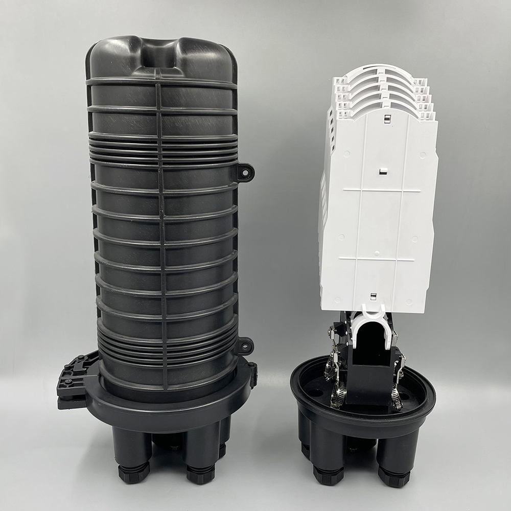
OYI-FOSC-D106M
The OYI-FOSC-M6 dome fiber optic splice closure is used in aerial, wall-mounting, and underground applications for the straight-through and branching splice of the fiber cable. Dome splicing closures are excellent protection of fiber optic joints from outdoor environments such as UV, water, and weather, with leak-proof sealing and IP68 protection. -
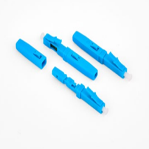
OYI G type Fast Connector
Our Fiber optic fast connector OYI G type designed for FTTH(Fiber To The Home). It is a new generation of fiber connector used in assembly. It can provide open flow and precast type, which optical and mechanical specification meets the standard optical fiber connector. It is designed for high quality and high efficiency for installation. Mechanical connectors make fiber terminaitons quick, easy and reliable. These fiber optic connectors offer terminations without any hassles and require no epoxy, no polishing, no splicing, no heating and can achieve similar excellent transmission parameters as standard polishing and spicing technology. Our connector can greatly reduce the assembly and setup time. The pre-polished connectors are mainly applied to FTTH cable in FTTH projects, directly in the end user site. -
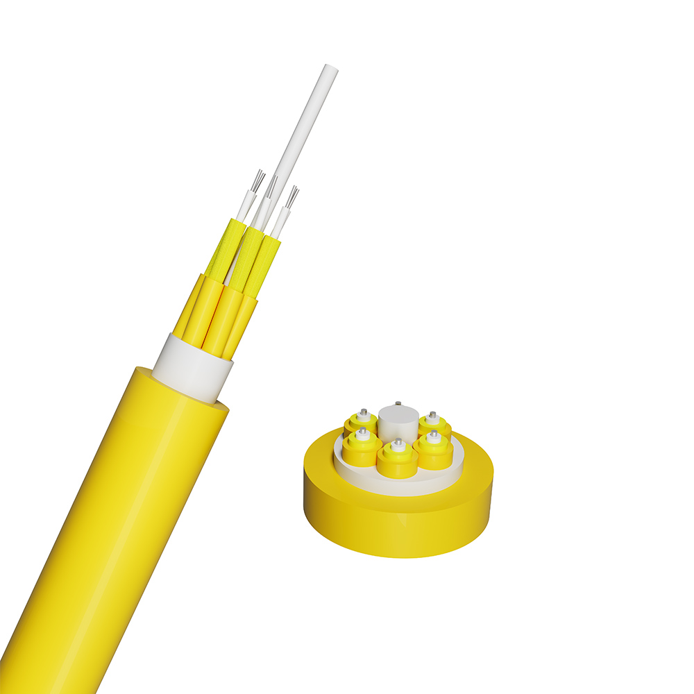
Multi Purpose Beak-out Cable GJBFJV(GJBFJH)
The multi-purpose optical level for wiring uses subunits (900μm tight buffer, aramid yarn as a strength member), where the photon unit is layered on the non-metallic center reinforcement core to form the cable core. The outermost layer is extruded into a low smoke halogen-free material (LSZH, low smoke, halogen-free, flame retardant) sheath.(PVC) -
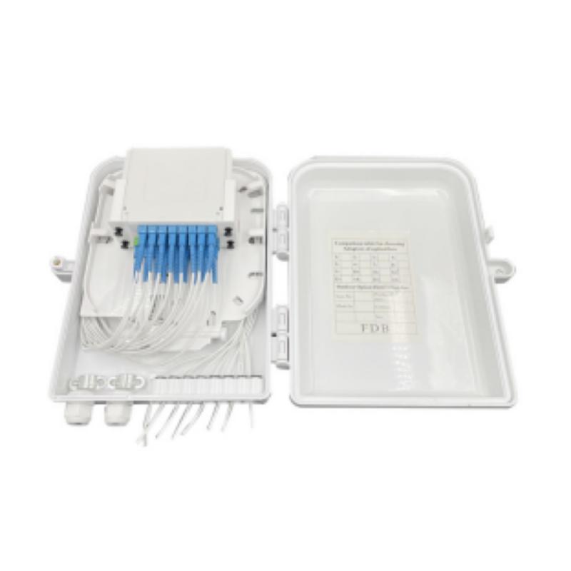
16 Cores Type OYI-FAT16B Terminal Box
The 16-core OYI-FAT16B optical terminal box performs in accordance with the industry standard requirements of YD/T2150-2010. It is mainly used in the FTTX access system terminal link. The box is made of high-strength PC, ABS plastic alloy injection molding, which provides good sealing and aging resistance. In addition, it can be hung on the wall outdoors or indoors for installation and use. The OYI-FAT16B optical terminal box has an inner design with a single-layer structure, divided into the distribution line area, outdoor cable insertion, fiber splicing tray, and FTTH drop optical cable storage. The fiber optical lines are very clear, making it convenient to operate and maintain. There are 2 cable holes under the box that can accommodate 2 outdoor optical cables for direct or different junctions, and it can also accommodate 16 FTTH drop optical cables for end connections. The fiber splicing tray uses a flip form and can be configured with 16 cores capacity specifications to accommodate the box’s expansion needs. -

GJYFKH
If you're looking for a reliable, high-speed fibre optic cable solution, look no further than OYI. Contact us now to see how we can help you stay connected and take your business to the next level.
