 0755-23179541
  sales@oyii.net
.png) 8618926041961
8618926041961
GJFJKH
Indoor Armored Optic Cable
GJFJKH
Product Features
1. Good mechanical and temperature performances.
2. Excellent crush resistance and flexibility.
3. Fire retardant sheath (LSH/PVC/TPEE) ensures fire resistance performance.
4. Suitable for indoor using.
STRUCTURE SPECIFICATION
|
Fiber Count |
1 |
2 |
4 |
6 |
8 |
12 |
24 |
|||
|
Tight Fiber |
OD(mm): |
0.9 |
0.6 |
|||||||
|
Material: |
PVC |
|||||||||
|
Strength Member |
Aramid Yarn |
|||||||||
|
Sheath material |
LSZH |
|||||||||
|
Armored Spiral Tube |
SUS 304 |
|||||||||
|
OD of Cable(mm)± 0.1 |
3.0 |
3.0 |
5.0 |
5.0 |
5.0 |
6.0 |
6.0 |
|||
|
Net weight ( kg/km) |
32 |
38 |
40 |
42 |
46 |
60 |
75 |
|||
|
Max.Tensile Loading (N) |
500 |
500 |
500 |
500 |
500 |
500 |
500 |
|||
Tight Buffer Color Code
|
NO. |
1 |
2 |
3 |
4 |
5 |
6 |
|
Color |
Blue |
Orange |
Green |
Brown |
Slate |
White |
|
NO. |
7 |
8 |
9 |
10 |
11 |
12 |
|
Color |
Red |
Black |
Yellow |
Violet |
Pink |
Aqua |
OPTICAL FIBER
1.Single Mode Fiber
|
ITEMS |
UNITS |
SPECIFICATION |
|
|
Fiber type |
|
G652D |
G657A |
|
Attenuation |
dB/km |
1310 nm≤ 0.4 1550 nm≤ 0.3 |
|
|
Chromatic Dispersion |
ps/nm.km |
1310 nm≤ 3.6 1550 nm≤ 18 1625 nm≤ 22 |
|
|
Zero Dispersion Slope |
ps/nm2.km |
≤ 0.092 |
|
|
Zero Dispersion Wavelength |
nm |
1300 ~ 1324 |
|
|
Cut-off Wavelength (λcc) |
nm |
≤ 1260 |
|
|
Attenuation vs. Bending (60mm x100turns) |
dB |
(30 mm radius,100 rings )≤ 0.1 @ 1625 nm |
(10 mm radius,1 ring)≤ 1.5 @ 1625 nm |
|
Mode Field Diameter |
μm |
9.2 ± 0.4 at 1310 nm |
9.2 ± 0.4 at 1310 nm |
|
Core-Clad Concentricity |
μm |
≤ 0.5 |
≤ 0.5 |
|
Cladding Diameter |
μm |
125 ± 1 |
125 ± 1 |
|
Cladding Non-circularity |
% |
≤ 0.8 |
≤ 0.8 |
|
Coating Diameter |
μm |
245 ± 5 |
245 ± 5 |
|
Proof Test |
Gpa |
≥ 0.69 |
≥ 0.69 |
2.Multi Mode Fiber
|
ITEMS |
UNITS |
SPECIFICATION |
|||||||
|
62.5/125 |
50/125 |
OM3-150 |
OM3-300 |
OM4-550 |
|||||
|
Fiber Core Diameter |
μm |
62.5 ± 2.5 |
50.0 ± 2.5 |
50.0 ± 2.5 |
|||||
|
Fiber Core Non-circularity |
% |
≤ 6.0 |
≤ 6.0 |
≤ 6.0 |
|||||
|
Cladding Diameter |
μm |
125.0 ± 1.0 |
125.0 ± 1.0 |
125.0 ± 1.0 |
|||||
|
Cladding Non-circularity |
% |
≤ 2.0 |
≤ 2.0 |
≤ 2.0 |
|||||
|
Coating Diameter |
μm |
245 ± 10 |
245 ± 10 |
245 ± 10 |
|||||
|
Coat-Clad Concentricity |
μm |
≤ 12.0 |
≤ 12.0 |
≤ 12.0 |
|||||
|
Coating Non-circularity |
% |
≤ 8.0 |
≤ 8.0 |
≤ 8.0 |
|||||
|
Core-Clad Concentricity |
μm |
≤ 1.5 |
≤ 1.5 |
≤ 1.5 |
|||||
|
Attenuation |
850nm |
dB/km |
3.0 |
3.0 |
3.0 |
||||
|
1300nm |
dB/km |
1.5 |
1.5 |
1.5 |
|||||
|
OFL |
850nm |
MHz .km |
≥ 160 |
≥ 200 |
≥ 700 |
≥ 1500 |
≥ 3500 |
||
|
1300nm |
MHz .km |
≥ 300 |
≥ 400 |
≥ 500 |
≥ 500 |
≥ 500 |
|||
|
The biggest theory numerical aperture |
|
0.275 ± 0.015 |
0.200 ± 0.015 |
0.200 ± 0.015 |
|||||
Mechanical and Environmental Performance of the Cable
|
NO. |
ITEMS |
TEST METHOD |
ACCEPTANCE CRITERIA |
|
1 |
Tensile Loading Test |
#Test method: IEC 60794-1-E1 -. Long-tensile load: 0.5 times the short-term pulling force -. Short-tensile load: reference to clause 1.1 -. Cable length: ≥ 50 m |
-. Attenuation increment@1550 nm: ≤ 0.4 dB -. No jacket cracking and fiber breakage |
|
2 |
Crush Resistance Test |
#Test method: IEC 60794-1-E3 -.Long-tensile load: 300 N/100mm -.Short-tensile load: 1000 N/100mm Load time: 1 minutes |
-. No fiber breakage |
|
3 |
Impact Resistance Test |
#Test method: IEC 60794-1-E4 -.Impact height: 1 m -.Impact weigh: 100 g -.Impact point: ≥ 3 -.Impact frequency: ≥ 1/point |
-. No fiber breakage |
|
4 |
Repeated Bending |
#Test method: IEC 60794-1-E6 -.Mandrel diameter: 20 D -.Subject weight: 2 kg -.Bending frequency: 200 times -.Bending speed: 2 s/time |
-. No fiber breakage |
|
5 |
Torsion Test |
#Test method: IEC 60794-1-E7 -.Length: 1 m -.Subject weight: 2 kg -.Angle: ± 180 degree -.Frequency: ≥ 10/point |
-. No fiber breakage |
|
6 |
Temperature Cycling Test |
#Test method: IEC 60794-1-F1 -.Temperature steps: + 20℃、- 10℃、+ 60℃、+ 20℃ -.Testing Time: 8 hours/step -.Cycle index: 2 |
-. Attenuation increment@1550 nm :≤ 0.3 dB -. No jacket cracking and fiber breakage |
|
7 |
Temperature |
Operating: -10℃~+60℃ Store/Transport: -10℃~+60℃ Installation: -10℃~+60℃ |
|
FIBER OPTIC CABLE BENDING RADIUS
Static bending: ≥ 10 times than cable out diameter
Dynamic bending: ≥ 20 times than cable out diameter.
PACKAGE AND MARK
1.Package
Not allowed two length units of cable in one drum. Two ends should be packed inside drum, reserve length of cable not less than 1meter.
2.Mark
Cable Mark: Brand, Cable type, Fiber type and counts, Year of manufacture and Length marking.

TEST REPORT
Test report and certification will be supplied on demand.
-

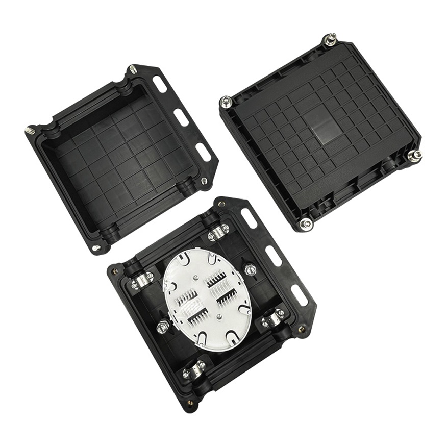
OYI-FAT-H16B4
Optical fiber distribution box 16 Cores fiber optic access termination box is able to hold up to 16 subscribers. It is used as a termination point for the feeder cable to connect with drop cable in FTTx network system. It integrates fiber splicing, splitting, distribution, storage and cable connection in one solid protection box. The optical distribution box is a solution that facilitates the installation of optical termination in branch networks for FTTH environments. -
OYI-FOSC HO7
The OYI-FOSC-02H horizontal fiber optic splice closure has two connection options: direct connection and splitting connection. It is applicable in situations such as overhead, man-well of pipeline, and embedded situations, among others. Comparing with a terminal box, the closure requires much stricter sealing requirements. Optical splice closures are used to distribute, splice, and store outdoor optical cables that enter and exit from the ends of the closure. The closure has 2 entrance ports. The shell of the product is made from ABS+PP material. These closures provide excellent protection for fiber optic joints from outdoor environments such as UV, water, and weather, with leak-proof sealing and IP68 protection. -

GPON OLT Series Datasheet
GPON OLT 4/8PON is highly integrated, medium-capacity GPON OLT for operators, ISPS, enterprises and park-applications. The product follows the ITU-T G.984/G.988 technical standard,The product has good openness, strong compatibility, high reliability, and complete software functions. It can be widely used in operators’ FTTH access, VPN, government and enterprise park access, campus network access, ETC.GPON OLT 4/8PON is only 1U in height, easy to install and maintain, and save space. Supports mixed networking of different types of ONU, which can save a lot of costs for operators. -

Anchoring Clamp PA600
The anchoring cable clamp PA600 is a high-quality and durable product. It consists of two parts: a stainless-steel wire and a reinforced nylon body made of plastic. The body of the clamp is made of UV plastic, which is friendly and safe to use even in tropical environments. The FTTH anchor clamp is designed to fit various ADSS cable designs and can hold cables with diameters of 3-9mm. It is used on dead-end fiber optic cables. Installing the FTTH drop cable fitting is easy, but preparation of the optical cable is required before attaching it. The open hook self-locking construction makes installation on fiber poles easier. The anchor FTTX optical fiber clamp and drop wire cable brackets are available either separately or together as an assembly. FTTX drop cable anchor clamps have passed tensile tests and have been tested in temperatures ranging from -40 to 60 degrees. They have also undergone temperature cycling tests, aging tests, and corrosion-resistant tests. -

Smart Cassette EPON OLT
The Series Smart Cassette EPON OLT are the high-integration and medium-capacity cassette and They are designed for operators’ access and enterprise campus network. It follows the IEEE802.3 ah technical standards and meets the EPON OLT equipment requirements of YD/T 1945-2006 Technical requirements for access network——based on Ethernet Passive Optical Network (EPON) and China telecommunication EPON technical requirements 3.0. EPON OLT possesses excellent openness, large capacity, high reliability, complete software function, efficient bandwidth utilization and Ethernet business support ability, widely applied to the operator front-end network coverage, private network construction, enterprise campus access and other access network construction.The EPON OLT series provides 4/8/16 * downlink 1000M EPON ports, and other uplink ports. The height is only 1U for easy installation and space saving. It adopts the advanced technology, offering efficient EPON solution. Moreover, it saves a lot cost for operators for it can support different ONU hybrid networking. -

GYFJH
The GYFJH radio frequency remote fiber optic cable. The structure of the optical cable is using two or four single-mode or multi-mode fibers which directly covered with low-smoke and halogen-free material to make tight-buffer fiber, each cable uses high-strength aramid yarn as the reinforcing element, and is extruded with a layer of LSZH inner sheath. Meanwhile, in order to fully ensure the roundness and physical and mechanical characteristics of the cable, two aramid fiber filing ropes are placed as reinforcement elements, Sub cable and the filler unit are twisted to form a cable core and then extruded by LSZH outer sheath (TPU or other agreed sheath material is also available upon request).
If you're looking for a reliable, high-speed fibre optic cable solution, look no further than OYI. Contact us now to see how we can help you stay connected and take your business to the next level.
